I've used the Figure 13C current source (post 21) and it works like a champ.
Wasn't the original (in the Walt Jung article) a 10M45S with an LM317, not an LM334?
Did you use the LM317 or the LF334 and it worked like a champ? I've used a DN2540 with an LM317 in the bottom position and it works fine, but I've never tried an LM334 with a DN2540, and I'd like to.
--
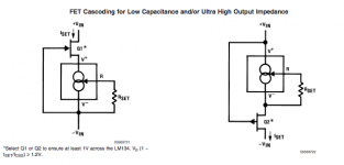
I would make the gate connection to the V pin of the LM334 as shown on the device manufacturer's datasheet, not the R pin. This is where the difference between the LM334 and the LM317 shows up.
It would probably work either way though...
Excuse a dumb *** but as far as I see the gate goes to V- in both examples (and to Rset). The difference is where the Rset resistor is placed as I can spot it. Either between Gate/V- and R or between Gate/R and V-
Or what is it I dont get?
Best
Staffan
I just finished assembling 10 of the lm334/dn2540 cascodes. 6 are for backup and 4 will load the final stage in my build.
Added a trimpot (200r) for fine tuning and used Fenris's suggestion to find Rset. I'll keep you all informed.
Added a trimpot (200r) for fine tuning and used Fenris's suggestion to find Rset. I'll keep you all informed.
Fentis could you post a complete schematic gor your lm334 based ccs? thanks!
Please do. And if you could tell a little about the applications to, if its for anode load, cathode bias or PS-filter or something else maybe?
Staffan
Stajo,
I use it primarily for anode loads below 5ma. Here is one example (sorry for the blurry pictures): http://www.diyaudio.com/forums/tubes-valves/211352-new-amp-13de7-se-hybrid.html
Walt Jung in his article (part 2, page 2) that Michael Koster referenced in post 16 notes that the LM317 needs 10ma minimum for regulation, so that's why for lower values I use the LM334.
The application requires 3mA and 5mA (both the supertex device and IXYS device will have to provide either one or the other).
The LND150 which is a TO-92 device might work a bit better than the DN2540 -- i just tried it out on the bench and with Fenris' circuit, and R=22 ohms I get ~3.1mA.
I did use the DN2540 + LM317 when I was building protos for one of SY's amplifiers -- worked very well. I didn't test the impedance of the current source, however, and used the doubled DN2540 which was used in the Impasse and HMN articles. It will be beastly hot tomorrow, so I can run the Z-test then, and as well run the Z-test on Fenriss' circuit.
Excuse a dumb *** but as far as I see the gate goes to V- in both examples (and to Rset). The difference is where the Rset resistor is placed as I can spot it. Either between Gate/V- and R or between Gate/R and V-
Or what is it I dont get?
Best
Staffan
The Rset goes between V and R. The cascode gate in both of the datasheet examples is connected to V, which is the recommended connection.
It's an earlier post I was referring to which has the gate connection through gate stopper to the R pin.
In this case it won't likely affect the operation as the Rset is so small compared with the impedance of the MOSFET gate.
Personally, I would go with the cascode gate connected to the V pin as the manufacturer recommends.
Last edited:
I have no drawing program here on my hollidaytrip but I guess you (Michael) prefers the left to the right, is that correct understood?

best
Staffan
best
Staffan
Last edited:
I have no drawing program here on my hollidaytrip but I guess you (Michael) prefers the left to the right, is that correct understood?
best
Staffan
Yes, the one on the left is consistent with the datasheet example, with the MOSFET gate stopper as needed.
I ran Formulize in this current range with one DN2540.2. What exactly is the correct value for each device (single IXYS and single SUPERTEX) to achieve 3mA and 5mA?
Simple equation in this range:
R= 2180/ Id(ma)
More Complex Equation:
R= 0.1646*Id + 2163/(Id - 0.08735) - 10.14
Go with the simple equation. There is enough variability in the devices that it will get you within 10%
I ran Formulize for the LND150 -- just using a resistor to set Vgs won't get you to 3.5mA of course (Idss is 1.69mA for the one I tested). Application note AN-12 on Supertex website has the complete theoretical formula, but this equation works within a few percent for Idss down to a 25 uA:
Rset= = 1010/(Id - 0.00642) - 701
Rset= = 1010/(Id - 0.00642) - 701
For the LND150:
Rset = 1010/(Id - 0.00642) - 701
Is Id = desired current to be sourced/sunk?
If yes, is that in mA or in A? (e.g. 2mA or 0.002A)
Can you give us an example of how to use that formula? I tried to use it to get a CCS current of 2mA and couldn't do it. I got negative results every time. Maybe I'm doing it wrong...
Help?
It's mAFor the LND150:
Rset = 1010/(Id - 0.00642) - 701
Is Id = desired current to be sourced/sunk?
If yes, is that in mA or in A? (e.g. 2mA or 0.002A)
Can you give us an example of how to use that formula? I tried to use it to get a CCS current of 2mA and couldn't do it. I got negative results every time. Maybe I'm doing it wrong...
Help?
The LND150 Idss is ~1.6 to 1.7mA, so a resistor at best will give Vgs=0
Dear all I have done some testing and here are my results.
Circuit testing method
1x supertex dn2540 + 2.2k stopper and multiturn 50k linear trimmer. I also added a protection R/C grid to the CCS device.
I used a 24v stabilized voltage supply - a 2.2k fictitious load and the CCS device in series.
I turned the trimmer all the way up and managed to achieve a 105mV drop across the 2.2k load. Given the constant load and constant supply voltage, vdrop is determined by current so I gathered we are looking at a minimum current draw of 0.000047A or 47uA
The same testing procedure with a 12v supply does not provide the same results. Maximum Vdrop across 2.2k resistor is 8.7v (as expected)
Turning the 50k trimmer all the way to 0r the current increases exponentially (obviously) and I can easily achieve 1mA or 2mA (as required in a tube design for example). For example a 4v drop across a 2.2k resistor load yields 1.8mA (as required in my design)
I am not sure how to corroborate these results (photo of DMM display?) but it works. Just stick the device on a testing bench and try it. It will work.
Will a lm334 based CCS device provide any appreciable benefits to this setup? better regulation perhaps?
P.s. I also tried LEDs as loads and the device worked perfectly.
Last edited:
I superimposed the values I got after measuring Idss and Vgst. For Idss, just short gate and source together and measure Id of 1.70mA. For Vgst, a 10 megOhm resistor from source to ground gave me about 100 nanoAmps (the level at which Supertex specifies the pinch off voltage) and Vgs of -1.52V. I checked up and down the table of values I ran a few days ago and the theoretical formula works within a few percent -- but you've got to do a bit of SQRT'ing etc., etc:
An externally hosted image should be here but it was not working when we last tested it.
What's an easy approximate calculation or Rset for a CCS to drive a VR150 glow tube? I'm using 58mA as an example.
R= 2180/ Id(ma) For 58mA: 38ohms
R= 0.1646*Id + 2163/(Id - 0.08735) - 10.14 For 58mA: 37ohms
Looks like voltage is 2.18v. That's similar to the IXYS part. Is the IXYS also suitable for 58mA?
R= 2180/ Id(ma) For 58mA: 38ohms
R= 0.1646*Id + 2163/(Id - 0.08735) - 10.14 For 58mA: 37ohms
Looks like voltage is 2.18v. That's similar to the IXYS part. Is the IXYS also suitable for 58mA?
I use single DN2540 at 50-100mA (aprox. 100....50V drop) in my measuring set...with large heat sink.Is the IXYS also suitable for 58mA?
- Status
- Not open for further replies.
- Home
- Amplifiers
- Tubes / Valves
- Supertex dn2540 CCS Rset trimmer value