Re: Please explain why you think they are similar.
is also not your proposed output stage. It's a complementary follower and it's operation is quite obvious.
Stee said:see this sample
is not a cascode
input signal made two waves in phase
the output is a mix of this two in load resistor
trought capacitors
Regards
is also not your proposed output stage. It's a complementary follower and it's operation is quite obvious.
Stee, we admire your tenacity, but read up a bit, download LT Spice and play a bit and then make som e proposals on the forum. Otherwise, you will have a lot of people laugfhing at you.
Start off with some conventional topologies first so you build some experience and understand how a basic amplifier works.
After this stage, there are many experts on the forum that can help guide you in the right direction
(PS: Feedback is actually a very good thing if applied wisely)
Start off with some conventional topologies first so you build some experience and understand how a basic amplifier works.
After this stage, there are many experts on the forum that can help guide you in the right direction
(PS: Feedback is actually a very good thing if applied wisely)
Bonsai said:Stee, we admire your tenacity.......................
Very nicely put...
I still cannot see how your output stage is supposed to work.
It still is nothing like the Quad circuit you quoted.
Andy
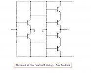
OK forget QUAD circuit
the target is:
a new architecture
(here in Italy we are inventors)
to have the sound of class A
but with AB bias
without Bridge
the philosophy is:
have two complementary devices instead one
working in phase for each rail
---> because in this way
the character of N and P device are superimposed
like class A
now, after your help, the project have a potential solution
please don't lose patience now😱
Stee
Very nice of you to pay homage to my recreated schematics - I have attached (I hope) another few which show the QUAD circuit element in context as part of the QUAD 34 disc input - You should see that what you have marked as output is actually a feedback point and the output is a voltage across R33 in the QUAD case and R100 for my circuit
Please do not give up on this but as others have said check your d.c. paths and be aware that Vbe changes will greatly affect the operating point if you do not allow for them
I have in fact made the "low noise inverting gain block" into a current output power amp for driving door magnets to excite guitar strings but that's a different story - The design can be made into a current amp to drive a single speaker but it is class A and has a class A inefficiency
As I said - Stick with it there are plenty of people here to help
Forget what I said above I can only attach part of the drawing - please check my website for the full QUAD 34 drawing
regards
Keith
Attachments
- Status
- Not open for further replies.