The SR on itself doesn't produce any 'sound quality'. It's sole purpose is to provide a stable, noisefree supply voltage.
If there would be hum on the supply, or if it would vary with the load/music, it might have an effect on sound quality, if that noise and hum would go from the rails into the output signal. But it is not only the supply voltage itself - the rectifier and ground wiring also has an effect. That is why I stress in the superreg documentation the need for a sensible ground connection taking the voltage differentially from the last reservoir cap to the SR to the circuit to be powered. I even provided a remote sense to improve the performance at the circuit to be powered.
So there are many factors that can be different between two regulators, their wiring and construction, etc, that can affect in some way the audible results.
Jan
Jan,
Thanks again for the guidance and input.
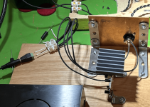
The SR01 has a sense circuit that is connected as near as possible to the load, you can see the 4 cables here connecting relatively closely to the load, 2 sense and 2 supply.
The actual grounding is from the USbridge, as the supply feeding the SR01 is just +ve and return so is effectively floating as the transformer secondary is not tied to anything.
The wall wart is also floating in this way until it picks up it's ground also from the USBridge unit.
What you have kindly reminded me of is the additional (optional) ground terminal on the USBridge that I neglected to fit since I took it off the shelf, so I will retry the comparison with this also connected, it did improve the sound to an extent and perhaps the SR will be more sensitive to this.
Maybe I should also consider making a safety earth connection to the return rail after the diodes?
Rich
Thanks again for the guidance and input.
The SR01 has a sense circuit that is connected as near as possible to the load, you can see the 4 cables here connecting relatively closely to the load, 2 sense and 2 supply.
The actual grounding is from the USbridge, as the supply feeding the SR01 is just +ve and return so is effectively floating as the transformer secondary is not tied to anything.
The wall wart is also floating in this way until it picks up it's ground also from the USBridge unit.
What you have kindly reminded me of is the additional (optional) ground terminal on the USBridge that I neglected to fit since I took it off the shelf, so I will retry the comparison with this also connected, it did improve the sound to an extent and perhaps the SR will be more sensitive to this.
Maybe I should also consider making a safety earth connection to the return rail after the diodes?
Rich
Attachments
# Troubleshooting Negative Super Regulator
My negative super regulator is currently not working properly (it was), while the positive side works correctly. I've spent quite some time trying to figure out what's wrong.
## Troubleshooting Steps Taken:
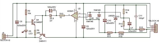
1. Replaced AD825, suspecting damage, but got similar values (few mV differences).
2. Removed and tested Q3 (D45H11) with a multimeter - it tested ok and was reinstalled.
3. Checked Q4 in-circuit - it tested Ok.
4. Checked for cold solder joints and reflowed suspicious connections.
## Details:
## Measurements:
Are there any known common issues with this particular part of the circuit that I should check?
Any suggestions would be appreciated.
My negative super regulator is currently not working properly (it was), while the positive side works correctly. I've spent quite some time trying to figure out what's wrong.
## Troubleshooting Steps Taken:
1. Replaced AD825, suspecting damage, but got similar values (few mV differences).
2. Removed and tested Q3 (D45H11) with a multimeter - it tested ok and was reinstalled.
3. Checked Q4 in-circuit - it tested Ok.
4. Checked for cold solder joints and reflowed suspicious connections.
## Details:
- Sense line is connected to the output of the SR.
- Load: 6.2 kOhm
- R14: 1.3 kOhm
- R13: 1 kOhm
- Other components per original schematic.
- Green LED is on.
## Measurements:
- Input voltage: -24.6V
- Output voltage: -21V
- Current across R8 (249R): 4.9mA
- Voltage at T junction (R11, LM329, R12): -6.93V
- AD825 Pin 3: -7.5V
- AD825 Pin 2: -8V
- AD825 Pin 6 (Output): -2.4V
- Q4 Collector: -9.3V
- Q4 Emitter: -23.9V
Are there any known common issues with this particular part of the circuit that I should check?
Any suggestions would be appreciated.
Attachments
I've used ordinary stock standard regulators (LM317/337) on very basic PCBs which have been available from an Australian source for over 20 years. These have been installed in well laid out chassis with onboard transformers and proper attention paid to grounding and cable routing. Never hear any system noise (neither buzz nor hiss) with my ears any further than an inch from the drivers. Only noise I ever hear is what's on a recording when the level is set too highly. Press Stop and that disappears. So I put out there that chasing one's tail around so-called super regulation to achieve something beyond audibility thresholds is not a worthwhile pursuit. 😴

A possibility could be D7 wrong way around or C5 shorted. It seems the opamp is trying to get the output voltage up, but doesn't quite get there.# Troubleshooting Negative Super Regulator
My negative super regulator is currently not working properly (it was), while the positive side works correctly. I've spent quite some time trying to figure out what's wrong.
## Troubleshooting Steps Taken:
1. Replaced AD825, suspecting damage, but got similar values (few mV differences).
2. Removed and tested Q3 (D45H11) with a multimeter - it tested ok and was reinstalled.
3. Checked Q4 in-circuit - it tested Ok.
4. Checked for cold solder joints and reflowed suspicious connections.
## Details:
- Sense line is connected to the output of the SR.
- Load: 6.2 kOhm
- R14: 1.3 kOhm
- R13: 1 kOhm
- Other components per original schematic.
- Green LED is on.
## Measurements:
The positive branch measures 6.9V at both pins of AD825
- Input voltage: -24.6V
- Output voltage: -21V
- Current across R8 (249R): 4.9mA
- Voltage at T junction (R11, LM329, R12): -6.93V
- AD825 Pin 3: -7.5V
- AD825 Pin 2: -8V
- AD825 Pin 6 (Output): -2.4V
- Q4 Collector: -9.3V
- Q4 Emitter: -23.9V
Are there any known common issues with this particular part of the circuit that I should check?
Any suggestions would be appreciated.
But the input voltage seems low at 24.6 if you want 24V out, that's not going to work. What's pin 6 of the opamp?
My recommendation is to get Vin up to a minimum of 27V, and if that doesn't fix it, check D7 for polarity and C5 for short.
Jan
He asked for ideas to fix his problem. Your post doesn't help.I've used ordinary stock standard regulators (LM317/337) on very basic PCBs which have been available from an Australian source for over 20 years. These have been installed in well laid out chassis with onboard transformers and proper attention paid to grounding and cable routing. Never hear any system noise (neither buzz nor hiss) with my ears any further than an inch from the drivers. Only noise I ever hear is what's on a recording when the level is set too highly. Press Stop and that disappears. So I put out there that chasing one's tail around so-called super regulation to achieve something beyond audibility thresholds is not a worthwhile pursuit. 😴
Jan
Sometimes the truth can be confronting, especially when you are invested in something. Not my problem. His problem could be resolved very easily by using basic proven regulation as I have suggested. Cheers.
A possibility could be D7 wrong way around or C5 shorted. It seems the opamp is trying to get the output voltage up, but doesn't quite get there.
But the input voltage seems low at 24.6 if you want 24V out, that's not going to work. What's pin 6 of the opamp?
My recommendation is to get Vin up to a minimum of 27V, and if that doesn't fix it, check D7 for polarity and C5 for short.
Jan
Thank you for your suggestions Jan. I've followed up on them and have some additional information:
To clarify, the expected output voltage is about -16V, not -24V. The current input voltage of -24.6V should be sufficient for this output, as it is for the positive regulator which produces around +16V.
D7 and C5 checks:
- I checked the orientation of D7, which was correct.
- I removed D7, tested it with a multimeter (it's OK), and reinstalled it.
- I checked C5, and it appears fine with no shorts.
Despite these checks, the behavior of the circuit remains unchanged.
For clarity, here are the opamp (AD825) pin voltages again:
- Pin 2 (inverting input): -8V
- Pin 3 (non-inverting input): -7.4V
- Pin 6 (output): -2.4V
Do you have any further suggestions based on this information?
Hi Jan,As a general rule, you would carry both the hot outputs as well as the individual grounds as far as possible to the powerd circuit, and connect the returns there.
You should avoid tying them at the rectifier/cap ground so you don't get ground loops that can cause hum and noise in the regulators. This is the basic principle, and why I put separate return grounds on the PCB so that the regulator can sense (and regulate) the voltage at the load point.
Any other method will degrade performance.
Use those ground returns on the diyaudiostore PCB!
Jan
Can you please give your expert opinion about these set up. It's not quite clear to me. Let asume i have a pcb with two op amps that i want to give each pin a separate super regulator.
In the example image i have only indicated the sense connections. You can image the power traces. Also there is a ground plane. But you can image traces also. You can delete the integrated PSU. It's just an example as common in practice.
What are the ideal sense return points? Like in fig.1, fig.2 (one ground point) or otherwise?
I have been playing with different type of sense cables and connections. I was surprised to find out that the type of cable and how the shield is connected makes a huge different in the sound. Good shielding also helps to avoid instability. I found differences (subjectively, by lack of an AP system) in dynamics and also in how I can hear the acoustic space. I would relate this to the output impedance and noise of the regulator respectively, but as said I can't measure this.
Now the question:
I get the best results when I use a balanced audio cable with the shield connected to the load side. This is contrary to the recommendation by Jan in his original article, but, to me, connecting the shield at the load side (the grounded source of the sense signal) seems to make more sense (pun intended) than connecting it to the floating input of the regulator. It also sounds better. Could the article be wrong?
(Of course I realize that it is virtually impossible that such a mistake would have gone unnoticed for decades. OTOH there is surprisingly little information on this on the internet, I've searched.)
Last edited:
I wanted to write a quick follow up on my endeavours with a Super Regulator. The SR01 which I purchased to try.
https://sjostromaudio.net/cart/buil...utput_voltage-33_v/42-voltage_reference-lm431
I installed a nice Parmeko transformer and a CRC into the regulator, using 13V as I needed to get 1.2A temporarily on start up. It all worked fine and at normal operation it was 500mA or so. I was powering a Allo USBridge.
I did not like the sound of this in my system, and have now replaced this with a 7805CK 3 pin regulator fed by the same CRC circuit. I have some nice capacitors either side of the Regulator and this sounds to me a lot better than the super regulator, so if anyone is interested to try one in your system let me know as I have no use for the SR01 which I purchased ready built. I am open to offers!
Have a good Christmas
@ABO
I haven't got to the stage you have but I've been thinking about the same issue(s) you raise when looking at the historical documentation: where to make all those connections.
If you don't just connect the senses to the power +/G/- connections on the amp board like many seem to do, and you want a better performing "point" on the circuit for the sense... maybe in the middle of the board... where does the sense ground go? This can be tricky especially with a balanced (twisted pair) cable. And then, as you point out, where does the shield go.
Looking down the road I was prepared to experiment a little. As you've done.
Did you pick a unique location to connect the senses?
I settled on connecting the shield at the sense- connection at the source (amplifier side). The shield was lef unconnected at the regulator. I am not 100% sure that this is universally best though.
Rane, for instance makes the folowing recommendation for an interconnect that resemble this application. But I maintain that the other way sounded better in my system.

Rane, for instance makes the folowing recommendation for an interconnect that resemble this application. But I maintain that the other way sounded better in my system.
I know that I am misunderstanding what you are saying here. The sense connection is at the 'source side'? The amplifier is not considered a source, but you may be referring to it as the beginning of the power supply? Sorry, I am not up to speed yet.
The diagram that you provided Is unclear to me as well in that first of all it is an adapter from balanced to single ended, but in this case used as a power connection I take it. Both ends look to be male so that throws me off a bit, and on the left of the diagram is part of a word that would have helped me understand. Is that word the end of Input or Output?
The diagram that you provided Is unclear to me as well in that first of all it is an adapter from balanced to single ended, but in this case used as a power connection I take it. Both ends look to be male so that throws me off a bit, and on the left of the diagram is part of a word that would have helped me understand. Is that word the end of Input or Output?
@Ixnay
ABO's language and that cable diagram are a little confusing. I'd ignore the cable drawing.
Best to refer to Walt and Jan's original drawing ABO shows in post 3671.
Sensing is achieved via a pair of conductors, shielded. often these two wires are connected at the device being powered at the same points that the feeds from the regulator board deliver power and return (ground).
Jan shows the shield connected at the regulator only. But ABO has obtained better performance by connecting the shield at the other end instead. Connecting a shield at only one end is often suggested. This usually works best the way Jan showed but circumstances vary. Try both and see what works best for you.
What you might miss, is that the interconnection for sense signal between the regulator and the load is identical to that of an interconnection between different audio components. Hence the comparison.
So, the input of the the sense connection is at the load side, from where the sense signal originates, and the output is at the regulator. I have connected the screen at the input, while Rane (and Jan btw) recommend connecting the screen at the output (regulator side).
Hope it makes more sense(!) now.
when you put it like that it makes a load of sense. (I can do that too!!)
by the way, how long are the wires connecting the regulator to the load PCB? Do you twist 'em?
by the way, how long are the wires connecting the regulator to the load PCB? Do you twist 'em?
Nice pun! If you want to go this route, you should use balanced interconnection cable.
btw in the original articles it is mentioned that stability should absolutely be checked with a scope. They weren't kidding. Even though my wiring was quite short, 10-15 cm, I could easily get the regs to oscillated by improper wire dressing during testing. Make sure to tightly bundle the grounds and supplies.
btw in the original articles it is mentioned that stability should absolutely be checked with a scope. They weren't kidding. Even though my wiring was quite short, 10-15 cm, I could easily get the regs to oscillated by improper wire dressing during testing. Make sure to tightly bundle the grounds and supplies.
- Home
- The diyAudio Store
- Super Regulator