I think, and that's only my thoughts, the guy who sells it, even its may a copy or just to draw attention, he got 20893 items sold on EBAY, He got 97.4% Positives, so I think there is more behind than only asking for Attention.This has nothing to do with Walt Jung or Linear Audio, typical trick to draw traffic.
You pays your dollar and you takes your chances, with no indication that it even does what they suggest.
Jan
BTW I have been in CHINA several times, and I can assure anyone here that those guys are trying to produce QUALITY PRODUCTS.
I would say anyone who has never been in CHINA and likes Electronics and Amplifier, make your next Trip to Guangzhou and Shenzhen. I'm also sure that each will be fascinated from what's going on in high-tech down there..
My 5 Cents to this issue..
Regards from Swiss
Pity the LME49710 is obsolete and unavailable.
Any other you tried with good results and no oscillation?
Hi
Have you tried LME49720, this one is new and available. then there is also LME79860, but this one in only available in SMD
May you try on of these..you will find that one on Ebay. I bought a few because of the output Voltage of 14.4 P-P Volts, which is 10 Volts RMS at Rail 44Volts.
I have both of them but not Tested yet. I'm late with my latest Project, still testing and so those IC's have to wait a bit..
Hope could be some help
Regards Chris
I think, and that's only my thoughts, the guy who sells it, even its may a copy or just to draw attention, he got 20893 items sold on EBAY, He got 97.4% Positives, so I think there is more behind than only asking for Attention.
I did ask for a schematic, to see if it was really a Jung regulator, but I got no answer.
@jan
PS to your edit:
I hear you and understand. I wasn't implying that it was your responsibility to test every permutation (except, perhaps, when you report that you kinda did). That would be nuts.
But if you reached into the junk drawer and used the first unit that came to hand and didn't see any reason to change it -- even though it was an odd-ish value -- then that would have been helpful info to share. (I apologize if you have; the thread is... epic)
And if you (or anyone) later tried a different junk drawer part -- and it worked too -- that would have been helpful to know to enrich the data set as actual experience deepens -- to add the next data point. Incrementalism.
Make sense? Reasonable?
Incidentally, after years of dithering I actually have boards on the way (with solder in part as a way to support diyaudio) so my comments/questions are a bit less academic that they've been in the past. Thanks for your patience with me over the years.
It's been many years and I tried to remember the history trail. I think that Walt originally came up with 120uF caps of a specific type and brand. Over the years that specific type became obsolete and I searched for a good equivalent, which I found and bought 100 of. Still have a lot of them, 120uF/50V, I don't know exact which type, I don't have that info where I am now.
Decoupling caps have an aspect that it rarely mentioned. Suppose you have a supply line with some ripple, and you put a cap on it to ground. What happens to the ripple? You expect it to become lower, and generally it does, but 'where does it go'? It represents energy and you can't destroy that, only transform it into another form. So, assuming the cap is an ideal cap with no losses, the result will be a ripple current from the supply line, through the cap, to the ground line.
And lots of bad things can result from increased ripple currents through ground lines.
So there is much more to it than ordering the most expensive super-duper cap you can find and slap it on the two wires.
Of course, after paying a mortgage installment for that super-duper cap, it makes your system sound soooo much better. Even if the objective performance actually became worse. ;-)
Jan
Last edited:
I did ask for a schematic, to see if it was really a Jung regulator, but I got no answer.
That's the most normal thing on EBAY.. there is very few who actually will answer your Question.. Still it doesn't mean that this seller is a bad guy..
It's a big Minus of EBAY Administration that they do not tell the Sellers to answer questions as a MUST, for selling their Stuff on Ebay..
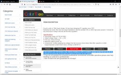
It's based on Jung.. Take a look at the screenshot, it's based on Jung not JUNG..
Greetings
Attachments
Last edited:
it's based on Jung not JUNG. Greetings
'Circuit is refer to Walt Jung design' can mean anything.
Jan
'Circuit is refer to Walt Jung design' can mean anything.
No doubt about it.
I just found a neat article set on selecting SR caps, in a drawer
Here is a link to the series of Audio Electronic LTEs on SR cap selection.
Thanks to Mark Johnson for the comments above on cap ESR, and to Jan for keeping a divergent discussion focused.
To summarize, the cap 100kHz ESR, size (uF), and rated voltage (V) all interact. Those old Panasonic units that jumped from the drawer onto the early SR PCBs were pretty much just what is/was needed for the above. See Fig. 1 of the link. They work well, as the ESR is just about as low as one should safely go. That is with a 100kHz ESR of 100 - 200milliOhms one should not get into trouble.
If you aren't sure of what this implies, simply use a close value/voltage. Note that 100uF/25V works as well as 120uF/25V (harder to get). For example, the Nichicon 100uF/25V part from their PJ series works OK (PN UPJ1E101MED). Be aware that some audio specified caps might be iffy for ESR, for certain conditions. The Nichicon 100uF/25V KZ types have an ESR of 0.15 ohms, while the 100uF/35V FG series has an ESR of ~0.2 ohms. Be aware that with most aluminum caps ESR rises with lower temps, and goes lower with high temps.
Enjoy!
Walt Jung
😉Nice. I read that Walt used the 120uF's as he happened to have some in a drawer. I happen to have some Nichicon KZ 220uF in a drawer with no use for them, now I have a use, in my next JD super reg, probably in the Singxer. 🙂 And I have a 120uF low cost for the output.
Here is a link to the series of Audio Electronic LTEs on SR cap selection.
Thanks to Mark Johnson for the comments above on cap ESR, and to Jan for keeping a divergent discussion focused.
To summarize, the cap 100kHz ESR, size (uF), and rated voltage (V) all interact. Those old Panasonic units that jumped from the drawer onto the early SR PCBs were pretty much just what is/was needed for the above. See Fig. 1 of the link. They work well, as the ESR is just about as low as one should safely go. That is with a 100kHz ESR of 100 - 200milliOhms one should not get into trouble.
If you aren't sure of what this implies, simply use a close value/voltage. Note that 100uF/25V works as well as 120uF/25V (harder to get). For example, the Nichicon 100uF/25V part from their PJ series works OK (PN UPJ1E101MED). Be aware that some audio specified caps might be iffy for ESR, for certain conditions. The Nichicon 100uF/25V KZ types have an ESR of 0.15 ohms, while the 100uF/35V FG series has an ESR of ~0.2 ohms. Be aware that with most aluminum caps ESR rises with lower temps, and goes lower with high temps.
Enjoy!
Walt Jung

Thanks for chiming in Walt. memory tends to become fuzzy after several decades ;-)
I would only add that for those who want to dimension their SRs for 24V or above, be conservative in the elcap voltage ratings. Use the 35V (or higher) types.
Jan
I would only add that for those who want to dimension their SRs for 24V or above, be conservative in the elcap voltage ratings. Use the 35V (or higher) types.
Jan
Thanks for chiming in Walt. memory tends to become fuzzy after several decades ;-)
I would only add that for those who want to dimension their SRs for 24V or above, be conservative in the elcap voltage ratings. Use the 35V (or higher) types.
Jan
Most certainly Jan. My approach is to let the Vraw input cap drive things. as it is always highest in terms of voltage stress. For Vout = 24V, a 50 or 63V cap is likely suitable, with peak Vraw duly considered.
Walt
The Super Reg is really good sounding reg, I was skeptical if an old design could still hold up against the new generation of high performance regs (Lt304X, TPS7AXXX), no one had commented on this before but the answer is very clearly yes IME.
I used OPA1611 seeing as its cheaper than AD825 and the LM49710 variant performed a bit better some areas compared to the AD825 in one of the articles, I can only assume the opa1611 would be a bit better than 49710 again.
Also used A-grade lm329 and Panasonic FR 150u for all except output cap, which was 100u 380mohm KEMET cap.
It was compared to TPS7A4701/TPS7A3301 powering OPA1612 IV/summing stages for Ak4499.
The SR is set to 12V to give it 5V to drop from 17V, I first compared the TPS7A at its original 15V vs at 12V and it sounded better at 15V, I guess the OPA are liking the higher rail voltage compared to higher input voltage for TPS7A.
It wasnt necessary to compare the sound more than once, the SR at 12V kills the TPS7A regardless and has only gotten better after some run time.
The TPS7A boards and SR boards were directly switched from the circuit, even same wires were used for each reg.
BTW I did not use sensing, it was just shorted out at the reg output, couldnt be bothered dealing with double the wiring for only a few cm long wires with low power circuits.
BTW 2, I checked the outputs of SR using very cheap scope since OPA1611 has not been tested extensively, with 2uS x 50mV grid there appeared to be no abberations on the outputs when connected to OPA board, cant confirm there isnt a problem at higher frequency or lower amplitude but IME oscillating circuits often do not sound very good so it isnt a worry.
Last edited:
BTW I did not use sensing, it was just shorted out at the reg output, couldnt be bothered dealing with double the wiring for only a few cm long wires with low power circuits.
The "sense" option is worth incorporating -- there is an voltage drop from the regulator to the device in use -- as a result you've just added meaningful impedance.
The real beauty of the SR is that the error amplifier puts so little of its signature back onto the supply rails. With an LM317 you can run an FFT and see that its sluggish error amplifier puts harmonics onto the supply rails. I didn't discover it, was reported to Jan by an observer from France:
Attachments
More than 1A is stretching it in the current setup. I am working on a higher-current version with thermal and short protection but that will be early next year or later.
Excited to see this new version of the super regulator when it's ready, especially with the additional protection circuits!
Can someone explain why a higher current version, using just a higher wattage pass transistor, wouldn't it be feasible?
More than 1A is stretching it in the current setup. I am working on a higher-current version with thermal and short protection but that will be early next year or later.
What you can do, if you have a few volts overhead available, is use a darlington for the pass device. Things like a TIP120/125 should work. But you must check for oscillations, I don't know how it will work out stability-wise. It might be prudent to leave off the cap across the feedback resistor.
And check the pinout, might be different, don't know.
Jan
I could use one higher current reg., count me in.
The "sense" option is worth incorporating -- there is an voltage drop from the regulator to the device in use -- as a result you've just added meaningful impedance.
The real beauty of the SR is that the error amplifier puts so little of its signature back onto the supply rails. With an LM317 you can run an FFT and see that its sluggish error amplifier puts harmonics onto the supply rails. I didn't discover it, was reported to Jan by an observer from France:
It wouldnt be very effective when the actual load points are all the OPA power pins and the traces from board power input to the OPAs likely adding as much impedance as the wires from reg.
Also I think I read earlier the sense line RC filter to is to ensure stability with long sense lines but is reducing bandwidth of the reg, with the sense line not in use could I possibly remove the filter and increase the bandwidth?
At the Chinese PCB fab where I buy a lot of my boards, the extra charge they apply for "2 ounce copper" is approximately the same as the extra charge they apply for "4 layer PCB". So when designing a new Super Regulator PCB to handle, let's just say, 3 amperes of output current, there are now more choices.
You can do a 2 layer PCB layout and use 2 ounce copper. This lets you pump twice as much current through each PCB trace, compared to standard 1 ounce copper boards.
You can also do a 4 layer layout and use the standard 1 ounce copper on the two outer layers, plus 0.5 ounce copper on the two inner layers. This lets you move all "signal" (low current) traces out of the way, by routing them on the inner layers. Now you've got the two outer layers completely free and open, to lay out nothing but big wide traces for the current carrying wires.
Which is better? You decide.
At the Chinese PCB fab where I buy a lot of my boards, the extra charge they apply for "2 ounce copper" is approximately the same as the extra charge they apply for "4 layer PCB". So when designing a new Super Regulator PCB to handle, let's just say, 3 amperes of output current, there are now more choices.
You can do a 2 layer PCB layout and use 2 ounce copper. This lets you pump twice as much current through each PCB trace, compared to standard 1 ounce copper boards.
You can also do a 4 layer layout and use the standard 1 ounce copper on the two outer layers, plus 0.5 ounce copper on the two inner layers. This lets you move all "signal" (low current) traces out of the way, by routing them on the inner layers. Now you've got the two outer layers completely free and open, to lay out nothing but big wide traces for the current carrying wires.
Which is better? You decide.
I will be designing a new pcb for my superregulators.
If I decide to have them made at a pcb company and the price + shipping to Brazil is fine, I would increase the area of all traces on both sides.
What specs does the pass transistor need to have for the superregulator?
- Home
- The diyAudio Store
- Super Regulator