The +/- 15v regulators turned out as a real hit 👍 Sounds great on day two.
It has been running for ~36hours. Elna silmic 25v/100uf on all cap positions.
For a couple of 5v regulators I'm about to make another order from Mouser 😎 .
So for now I'm ordering:
LM-4040-2.5 (D5)
2,5v zeners (D2)
AD817 opamps
If I'm missing something here please let me know 🤔
I already have the resistors and such.
I also wonder if the opa1642 could be a contender for the opamp ?
It says minimum 4,5v single supply.
opa1642
Maybe use a green LED and 1n4149 in series for D5 and D2 - much quieter
i used an Semitec E452 jfet current source diode to feed D5 instead of the R5 resistor - you won’t get the full
4.5 ma current because of the low voltage drop (2.5 v) on the E452 it might be 3ma, but its enough. the E562 would be about 4 ma if its in stock. The LEDs are a quieter with the higher current but are always lower noise than the 4040, 431, 329 , the dynamic impedance I’m not so sure of, which is why you want a current source. For higher voltages (24 and 30 VDC) I use Walt’s 5486 Cascode of the Semitec jfets
Last edited:
Thanks.Maybe use a green LED and 1n4149 in series for D5 and D2 - much quieter
i used an Semitec E452 jfet current source diode to feed D5 instead of the R5 resistor - you won’t get the full
4.5 ma current because of the low voltage drop (2.5 v) on the E452 it might be 3ma, but its enough. the E562 would be about 4 ma if its in stock. The LEDs are a quieter with the higher current but are always lower noise than the 4040, 431, 329 , the dynamic impedance I’m not so sure of, which is why you want a current source. For higher voltages (24 and 30 VDC) I use Walt’s 5486 Cascode of the Semitec jfets
I will keep this in mind.
Hello, everyone,
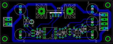
I want to build a pair of boards myself.
That's why I tried to get the layout one-sided.
Do you think there are any downsides or limitations to be expected from the layout changes?
Thanks and greetings Martin
I want to build a pair of boards myself.
That's why I tried to get the layout one-sided.
Do you think there are any downsides or limitations to be expected from the layout changes?
Thanks and greetings Martin
Attachments
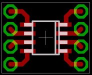
The thru hole footprint for IC1 doesn't quite look correct -- it appears, visually, to have excessive spacing between the two vertical rows of four pads-with-drill-holes.
For reference, here's a footprint of a DIP-8 opamp on a PCB I designed recently. Blue is the top silkscreen (comment text) layer, and gold is the solder pads which are on both top and bottom copper layer. I've had boards built using this footprint, and it perfectly matches DIP ICs and DIP sockets.
_
Attachments

Yes I know. I made a SOIC8 -> DIP-8 adapter, it's a bit wider so you can solder the SOIC8 in such a way that you don't need vias.
See small picture above...
See small picture above...
I have put together two 5v regulators (2.2) apart from the 15v+/- ones
that seem to be working just fine. I have tried them with opa604, ad817
and the op1641 opamps. They all seem to be be working with just some
minor ac-ripple on output. There is no load connected yet so I'm wondering
on how to verify if any of these opamps should be avoided. They all measure
between 0,027 and 0,04mV ac on a fluke 189 DMM.
I will try to add some load later this evening to see if that changes anything.
Tips and tricks are welcome.
OPA1641 is the best choice of the above (lowest noise). For 5V, I use LT6202, but jfet op.amp is a better choice, because Walt's last upgrade can be used.I have put together two 5v regulators (2.2) apart from the 15v+/- ones
that seem to be working just fine. I have tried them with opa604, ad817
and the op1641 opamps. They all seem to be be working with just some
minor ac-ripple on output. There is no load connected yet so I'm wondering
on how to verify if any of these opamps should be avoided. They all measure
between 0,027 and 0,04mV ac on a fluke 189 DMM.
I will try to add some load later this evening to see if that changes anything.
Tips and tricks are welcome.
An Improved Reference Filter for Audio Regulators
@jan.didden
is it recommended to keep the regulator away from the rectifier and reservoir capacitors?
or would it not be a problem if implemented together on the pcb?
is it recommended to keep the regulator away from the rectifier and reservoir capacitors?
or would it not be a problem if implemented together on the pcb?
It will not be a problem if you keep the input and ground lines separately. So connect the reservoir cap output voltage to the input pins on the reg board, and connect the load to the reg output pins. Do not take the reservoir cap ground leads to the load.
Jan
Jan
Thanks for your answer! 🙂 Understood! 👍It will not be a problem if you keep the input and ground lines separately. So connect the reservoir cap output voltage to the input pins on the reg board, and connect the load to the reg output pins. Do not take the reservoir cap ground leads to the load.
Jan
Another question... following the thread I noticed that film and ceramic capacitors are not allowed in the regulator... but,
at load they are not a problem, due to the resistance and inductance of the cables, right?
Sometimes we have small 3.3v/1v regulators in the load... and they have an LC arrangement (attached image).
Should this inductor be removed and keep only the capacitors?
Attachments
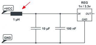
The L at the input is OK. You only have to make sure there's a lossy cap at the output, so no film or ceramic there. A bog standard electrolytic is best at the output.
Jan
Jan
So I measured for ac ripple with the opa604, ad817 and the op1641 again.
With some load this time, 120mA / 470uf on output.
Spanned from 0,068-0,074 mV so I would call them almost identical for this simple test.
With some load this time, 120mA / 470uf on output.
Spanned from 0,068-0,074 mV so I would call them almost identical for this simple test.
If that is ripple at the output something is wrong. If it was at the input, the opamp should not make any difference. What is the input and output voltage?
I measured a Texas instruments TPS7A4701EVM-094 just now and
that gave me 0,052mV ac, so maybe the fluke 189 is malfunctioning.
With shorted probes I seem to get 0,022mV ac 🤔
that gave me 0,052mV ac, so maybe the fluke 189 is malfunctioning.
With shorted probes I seem to get 0,022mV ac 🤔
Input voltage @ the regulator is 10v, output is 5v with no load.
It drops to 4,8V with load but it doesn't seem to matter how much
load . I have tried it from 40mA up to 210mA without
any difference. The SR's measure identical AC regardless of differences
in load as well.
Edit: Didn't see your post, but it seems they are working as expected then 🙂
It drops to 4,8V with load but it doesn't seem to matter how much
load . I have tried it from 40mA up to 210mA without
any difference. The SR's measure identical AC regardless of differences
in load as well.
Edit: Didn't see your post, but it seems they are working as expected then 🙂
Yes but the drop to 4.8V is strange. At which points do you measure the output voltage? What do you use for the ref and what in series with opamp output. What opamp?
Jan
Jan
- Home
- The diyAudio Store
- Super Regulator