I am novice, but learning fast. I would like to install a super regulator in a Crown IC 150A. This was recommended by member Jackinnj. Could someone provide more detail on the exact wiring for this upgrade.
Remove IC30.
Where IC30 was - Pin 6 is your unregulated Pos Voltage and Pin 4 is unregulated Neg Voltage to feed your 18V SuperRegulator
To bring back the regulated voltage:
You should see 2 wire links about an inch long, close to where IC30 was.
The wire link that connects to where Pin 7 was - this is where your Pos voltage from the superReg will return.
The other wire link that goes to pin 5 is the Neg return.
Since you will be bringing back the voltage and the sense lines for each, and the pc board holes will probably not be big enough, you can attach both V and sense lines to the wire link.
Lift the side of the wire link closest to IC30.
Doing this will remove all the parts associated with the old reg out of the circuit
Cut the link just long enough to make a small loop with it.
Attach your return wires from the SR to the loop.
For your ground connection - you will see a trace that runs under where IC30 was. Follow it up to above where IC30 was and you should see an open Pad in between the 2 wire links to connect your grounds to.
You will only have to connect the SR ground output ( but both Pos and Neg )
If you ever need to return your unit to stock- you would just need to install new wire links and IC30

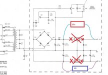
With an LM329 6.9 VREF ( D5 and D10 )
R6 and R13 = 1.2K
R7 and R14 = 806
For D2 and D7 use a 1N5239B
R6 and R13 = 1.2K
R7 and R14 = 806
For D2 and D7 use a 1N5239B
since I am a noobie, I am still having difficulty confidently making connection to main board. Also are you still using the NE3554/opamp, did you need to need to alter the circuit (pin 5,6,8). Thanks for the pic.
I left pins 5,6,8 alone. I modified the output sections to use a NE5534 and BUF634 as a composite amplifier. These replace IC130, IC230 which were LF356H (an old JFET opamp). FWUW, TI has subsequently introduced the BUF634 with BUF634A which is superior. I should probably use a better opamp than the 5534.
If you remove the two regulator chips, you can wire up as shown:
If you remove the two regulator chips, you can wire up as shown:
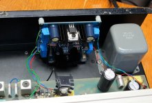
Attachments
- Home
- The diyAudio Store
- Super regulator question