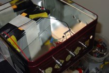
Here's the picture of my new "Danish Setup" -- it has taken approximately 3 months to undo the damage to my physique caused by eating a tin of these cookies purchased around Christmas:
While the big tin will hold a couple of SLA batteries, it's also a magnet for a.c. line fundamental and harmonics.
The Colin low noise preamp is a bit lower noise, but isn't as accurate as the one suggested by WJ. I hope to build the Jim Williams amplifier from AN-124 this weekend.
An externally hosted image should be here but it was not working when we last tested it.
While the big tin will hold a couple of SLA batteries, it's also a magnet for a.c. line fundamental and harmonics.
The Colin low noise preamp is a bit lower noise, but isn't as accurate as the one suggested by WJ. I hope to build the Jim Williams amplifier from AN-124 this weekend.
Hey Jack, I built that one too, with the LT1028, but then moved onto a simple 4 x 2sk170v first stage and 1 x 2sk170bl second stage. Nice gain of 60db, no need for dual supply (works on 24V, 2 x 12V lead acid batteries), and I think has lower noise than the opamp one. I became more fond of the crackers square boxes, bigger, taller, fits my batteries 😀
The problem I have with both is calibrating it for 60db gain with low tolerance.
The problem I have with both is calibrating it for 60db gain with low tolerance.
Attachments

The 2SK170 has pretty high input capacitance -- so when you parallel devices the f3 is reduced. The BF862 is only available in SOT23 but has higher transconductance (45 mS) vs 22mS) and lower Ciss (10pF vs 30pF). Because the BF862's transconductance is so much higher (2x the K170) you can really get out of the weeds when you parallel devices.
In these very high gain amplifiers even a tiny of bit of wire will pick up all kinds of radiation. So the design has to be quite compact and the power supply or battery leads bypassed.
In these very high gain amplifiers even a tiny of bit of wire will pick up all kinds of radiation. So the design has to be quite compact and the power supply or battery leads bypassed.
The 2SK170 has pretty high input capacitance -- so when you parallel devices the f3 is reduced.
Sorry, what's f3?
The BF862 is only available in SOT23 but has higher transconductance (45 mS) vs 22mS) and lower Ciss (10pF vs 30pF). Because the BF862's transconductance is so much higher (2x the K170) you can really get out of the weeds when you parallel devices.
Yes, I'm aware of the lower capacitance bf862, but had a bunch of sk170 on hand so I used them. I might redo it with the bf862, but maybe not, it seems fine,
In these very high gain amplifiers even a tiny of bit of wire will pick up all kinds of radiation. So the design has to be quite compact and the power supply or battery leads bypassed.
I agree, I bypassed the battery leads right at the sk170 load. Are you referring to the actual part leads that they can be made shorter too? I wasn't too worried because I also use a lid on the box.
Sorry, what's f3?
Here are 2 amps with identical gain -- you can see that the one with several JFETs rolls off more quickly than one with only one device.
An externally hosted image should be here but it was not working when we last tested it.
We filter the high frequency anyway, at least JW does, band pass 10Hz to 100kHz. Beyond a few hundred kHz do we even want to amplify?
Jack, how do you calibrate your 60dB gain low noise amplifier?
I have an idea for building a high precision simple AC calibrator in the same amplifier box so that when 1V is measured, with high certainty I can say that the original signal is 1mV. Would you be interested in that?
I have an idea for building a high precision simple AC calibrator in the same amplifier box so that when 1V is measured, with high certainty I can say that the original signal is 1mV. Would you be interested in that?
Jack, how do you calibrate your 60dB gain low noise amplifier?
I have an idea for building a high precision simple AC calibrator in the same amplifier box so that when 1V is measured, with high certainty I can say that the original signal is 1mV. Would you be interested in that?
Since we're measuring noise power, we're really integrating the area under a curve, and need to know the bandwidth at each measurement. WJ used an approximation of "48 root F" as the divisor for a 4th order filter with a Q of 5 to calculate nV/root Hz. We don't know anything with absolute certainty, but we can estimate how accurate with statistics.
I like the idea of using a low noise amplifier's bias current to calculate measurement accuracy:
Analysis and Measurement of Intrinsic Noise in Op Amp Circuits - Part X: Instrumentation Amplifier Noise - audio/videoZONE
Thanks for the link. My question was about something else. We build a 1000x (60dB) low noise amplifier. Even using 1% resistors for setting the gain, you will see that JW allows for adjustment in the second stage gain, using a 2k variable resistor. How do you calibrate the amplifier to be as close as possible to 60dB? And then, is the gain stable over time (temperature, battery voltage dropping, etc.).
If the 60dB gain figure is specified with +- 0.xyz dB from A to Z frequency then I can simply measure power of the amplified noise with a spectrum analyzer (which now doesn't have to be so fancy) and adjust the result for the 60dB amplification, and if I trust my 60dB tolerance specs I do have an idea of the error.
Of course the assumption here is that the amplifier self-noise is significantly lower than the noise to be measured.
In order to do this, I want to calibrate and trust the specifications of the 60dB amp. That's what I was talking about, and was asking if you're interested in a discussion about this calibration. I was thinking of a new thread on the subject.
... and I was thinking this is a feedback amp with gain set through a feedback network, guaranteeing 60dB.
Hmmm...
jd
Hmmm...
jd
Sure one can argue that using precision resistors the gain is guaranteed, but that's not sufficient to me. Also, setting the gain by watching the input and output signal on a scope or measuring it with a voltmeter is as precise as the instrument that measures it.
Here's what I have in mind. Use a micro-controller and a highly stable precision reference like LTC6655, to generate a 1.25V p-p sine wave. Feed this into a voltage divider using two precision resistors like 10k series 10R, to obtain a signal of 1.25mV p-p. Feed this into the 60dB amplifier and compare the output to the original 1.25V output from the micro-controller. In fact one could use an analog dial to search for the null. Build this so that it is a switchable mode Calibrate-Amplify. This same setup can be used to calibrate the AC voltmeter too, being in effect a precise AC voltage generator. I think I worked out the details, that's why I was asking if people would be interested in a thread about it. Anyway, I think I'll just open a thread when I got it working.
Here's what I have in mind. Use a micro-controller and a highly stable precision reference like LTC6655, to generate a 1.25V p-p sine wave. Feed this into a voltage divider using two precision resistors like 10k series 10R, to obtain a signal of 1.25mV p-p. Feed this into the 60dB amplifier and compare the output to the original 1.25V output from the micro-controller. In fact one could use an analog dial to search for the null. Build this so that it is a switchable mode Calibrate-Amplify. This same setup can be used to calibrate the AC voltmeter too, being in effect a precise AC voltage generator. I think I worked out the details, that's why I was asking if people would be interested in a thread about it. Anyway, I think I'll just open a thread when I got it working.
Of course the assumption here is that the amplifier self-noise is significantly lower than the noise to be measured.
Statistics again -- since you're making an RMS measurement (the square root of the sum of the squares of device and amplifier noise) once the amplifier is 70% less noisy than the device under test, you are at +/- 2 sigma.
Thanks again Jack, but I tell you, I'll leave this to you guys that are more experienced. To me little makes sense, messages are cryptic, I don't know. Are you talking about +-2 standard deviation? Well, I skimmed the article and will go over it again in more detail.
I'll start another thread about what I mentioned before, and will pull back here because I'm getting nowhere. Good luck with your noise measurements.
I'll start another thread about what I mentioned before, and will pull back here because I'm getting nowhere. Good luck with your noise measurements.
The 95% confidence level -- I just wanted to point out that you don't have to get down to femto-Amperes or pico-Volts for measurements which are relevant. The SSM2019 amplifier is fine, so are the ones you describe.
Sure one can argue that using precision resistors the gain is guaranteed, but that's not sufficient to me. Also, setting the gain by watching the input and output signal on a scope or measuring it with a voltmeter is as precise as the instrument that measures it.
Here's what I have in mind. Use a micro-controller and a highly stable precision reference like LTC6655, to generate a 1.25V p-p sine wave. Feed this into a voltage divider using two precision resistors like 10k series 10R, to obtain a signal of 1.25mV p-p. Feed this into the 60dB amplifier and compare the output to the original 1.25V output from the micro-controller. In fact one could use an analog dial to search for the null. Build this so that it is a switchable mode Calibrate-Amplify. This same setup can be used to calibrate the AC voltmeter too, being in effect a precise AC voltage generator. I think I worked out the details, that's why I was asking if people would be interested in a thread about it. Anyway, I think I'll just open a thread when I got it working.
I'm sure you can get it to work, but I don't follow the importance of super-accurate gain numbers. So the nominal 60dB gain is really 59dB, or 61dB, so what?
I wouldn't worry about that.
jd
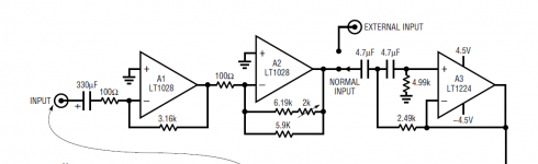
Here Jan, this is the subject. See A2 feedback resistors. I wish there were guarantees, but practically... ???
Iko,
I saw this post after my previous post. So, why the var resistor? Why not calculate the total gain for 60dB and set it there? With those opamps you probably get better than 0.1% without any adjustment.
jd
because 3k16:100r twice, gives a gain of 1063 times or +60.53dB.So, why the var resistor?
The resistor ratio for the second stage is 29k67:100r for close to +60dB gain and only if all the gain setting resistors are 0.1% tolerance.
Use 1% and dial in the gain with the VR. One can then swap it to fixed resistors, for longer term stability.
because 3k16:100r twice, gives a gain of 1063 times or +60.53dB.
The resistor ratio for the second stage is 29k67:100r for close to +60dB gain and only if all the gain setting resistors are 0.1% tolerance.
Use 1% and dial in the gain with the VR. One can then swap it to fixed resistors, for longer term stability.
I see. You could use a next-higher value for the stage 2 feedback resistor and calculate a parallel resistor to get to exact 60dB....
Within 0.1% of course.
jd
and the difficulty as Iko has pointed out is how to determine the final gain that has been created.
Using +-0.1% resistors in two gain stages will give 60+-0.04dB accuracy. That's good enough for me. But how do we measure/confirm it?
Using 1% resistors gives a tolerance of ~+-0.4dB.
Using +-0.1% resistors in two gain stages will give 60+-0.04dB accuracy. That's good enough for me. But how do we measure/confirm it?
Using 1% resistors gives a tolerance of ~+-0.4dB.
- Home
- Amplifiers
- Power Supplies
- Super Regulator, collecting the facts