Hi Regal,
As far as I understand, the TDA1541 needs 0.000V between its analog ground and its output pins. Here are quick things I would think of :
1° You set the analog ground to the converter's ground and create a -3V power supply to connect the cathod to.
2° You set the TDA's analog ground to +3V
What do you think ?
greg
I think the TDA 1541 should have digital ground and analog tied together it isn't a galvanic isolation device, also you would have to set the TDA analog supply to +17V, too out there for me.
Great
can you upload your LTC file please , to take a look
It seems a "kiss" version as i like
Here you go.
Attachments
Hi
@Tazzz,
Isn't your schematic a bit like the I/V converter used in Eric Janueda's system High End Audio - Jundac One
Well, I am quite sure it is a very efficient circuit, but our game was to make the signal to cross only valves 😱 The super common gate schematic can also be built with JFET with better results by far. That's a very simple toy with great results, we had no pretention saying this is the best I/V in the world (which surely is not).
@Regal, special for you:


The opamp ensures the cathod is tied to 0V (-2µV in the simulation).... but it means -5V PSU + +-15V for the opamp, complicated PSU unit. Still, signal does only go trough tubes 🙂
greg
@Tazzz,
Isn't your schematic a bit like the I/V converter used in Eric Janueda's system High End Audio - Jundac One
Well, I am quite sure it is a very efficient circuit, but our game was to make the signal to cross only valves 😱 The super common gate schematic can also be built with JFET with better results by far. That's a very simple toy with great results, we had no pretention saying this is the best I/V in the world (which surely is not).
@Regal, special for you:
The opamp ensures the cathod is tied to 0V (-2µV in the simulation).... but it means -5V PSU + +-15V for the opamp, complicated PSU unit. Still, signal does only go trough tubes 🙂
greg
Hi Chanmix 😉
Can you put your files
to play with 😱
And a short speech on Audiyofan.org to wake audiophile's french people
Enjoy
Can you put your files
to play with 😱
And a short speech on Audiyofan.org to wake audiophile's french people
Enjoy
Hi again Chanmix
Nice impedance curve but the version without AOP is better
for phase's curve
Best IV converter surrely not but FREE design for sure
and simple , no exotic or esoteric caps , no expansive valve,
no Xformers (expansive or not) except for power supply
we don't spend much money to get a lot of fun 😀
Nice impedance curve but the version without AOP is better
for phase's curve
Best IV converter surrely not but FREE design for sure
and simple , no exotic or esoteric caps , no expansive valve,
no Xformers (expansive or not) except for power supply
we don't spend much money to get a lot of fun 😀
Hi again Chanmix
Nice impedance curve but the version without AOP is better
for phase's curve
Mmmh isn't the phase important only at output ?
Best IV converter surrely not but FREE design for sure
and simple , no exotic or esoteric caps , no expansive valve,
no Xformers (expansive or not) except for power supply
we don't spend much money to get a lot of fun 😀
There is a power button for pleasure 😉
greg
Mmmh isn't the phase important only at output ?
Exactly , i'm stupid , I stayed on the curve of Vin as an Eeyore
Forget it
Oh yesss ..... with a intense blue LEDThere is a power button for pleasure 😉
greg
Hi,
Here is a discover we made maybe some of you know already. Our I/V valve converter works pretty well with the TDA1543 and the few who tried it were quite amazed with the sound this cheap DAC could output.
BUT ... Yves, after he built his version, noticed a gain loss at 20kHz ... -3dB 🙁 After he tried everything to understand what was going on he found that this was caused by the DAC itself.
In order to produce a continuous signal, DACs use a blocker mechanism that keep the output current level between 2 digital data. These blockers also work like a filter with a bandwith shaped in a sin(x)/x form with a minimum at the sampling frequency and -3dB at half this frequency. NOS DACs have a sampling frequency of 44,1kHz so -3dB is roughly 20kHz.
Of course there are ways to ovoid this problem, the first solution is to ... oversample and raise the -3dB limit way over 20kHz. You can also use filters to reshape the signal after or before the DAC. A last solution is to keep the things as is just because sound is good ... that's what I chose 😎
I thought maybe this could help others.
greg
It looks like John Broskie published a blog post about the same kind of I/V converter with a lot of examples 😎
Hi all
We also work on a solid state version for TDA1543 and TDA1541
The IVPBen works just with different voltage
I listen the TDA1541 version everyday integrated in my Philips's drive
Have a look on this here Audiyofan.org • Afficher le sujet - Comvertisseur super kiss pour 1543
see the other page for more info, but in french 😡
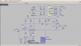
the scheme
We also work on a solid state version for TDA1543 and TDA1541
The IVPBen works just with different voltage
I listen the TDA1541 version everyday integrated in my Philips's drive
Have a look on this here Audiyofan.org • Afficher le sujet - Comvertisseur super kiss pour 1543
see the other page for more info, but in french 😡
the scheme
Attachments
TDA1541 offset
Hi Regal, I haven't read the entire thread on this topic, but I recall Nakamichi did some distorsion measurements on the TDA1541 which gave a minima at an offset of 55mV on the output of the TDA / input of the I/V converter. Has anyone else commented on this ?
Hi Regal, I haven't read the entire thread on this topic, but I recall Nakamichi did some distorsion measurements on the TDA1541 which gave a minima at an offset of 55mV on the output of the TDA / input of the I/V converter. Has anyone else commented on this ?
I believe they are the same topology really, the one I posted I think was the first version, then the 6F12P was replaced with the Mofset.
Chanmix mentioned the all tube 6F12P version as being so similiar to the hybrid as to not be audibly different, but I'm getting a much higher input impedance on the sim than he reports.
I like the 6F12P version because it seems easier to integrate with the TDA1541, which wants to see 0VDC on its output and it draws 2ma of current (offset).
- Status
- Not open for further replies.
- Home
- Source & Line
- Digital Line Level
- Super common gate valve I/V converter for TDA1543