Quick question.
Since neo magnets have become increasingly more expensive, are they really worth the extra $$$. I know that specs are a little different, but...
In a Synergy horn with two or four mids, this would mount to be a considerable price difference!
/Thomas
I'm price sensitive and normally chose the ferrite model over a neodymium one. I can normally justify neodymium for the compression driver, but it’s a hard sell for the mids and woofers. When the price of neodymium shot through the roof last year, it made me gun shy to design anything using them.
This is also the reason to why I've chosen either the Faital PR200 or W8N8-150. They also come in 16 ohm, sacrificing some sensitivitity. The obvious candidate would be the B&C-8NDL51 but 8 ohms only.
/Thomas
Don't overlook the Faital 8FE200. The car audio guys love this driver. They beat the heck out of them, so it is a tougher and better made driver than it might appear. It is available in 4 and 8 ohms. A pair of the 4 ohm models could be ran in series for an 8 ohm load. The higher Q would aid in your desired sealed alignment.
I've been looking at that one too, if only Faital could manage to get their specs synchronized. On their own website the FE200 looks af little week, especially the 8 ohm version.
FaitalPRO | Product Comparison
/Thomas
FaitalPRO | Product Comparison
/Thomas
A significant advantage of using neo drivers is the weight, though. If you use 4 of each kind of driver with ferrite magnets, your synergy horn can end up being pretty heavy.
But I also tend toward ferrite because of cost. It would be different if the design were to be commercial and needed to be shipped around.
But I also tend toward ferrite because of cost. It would be different if the design were to be commercial and needed to be shipped around.
Edge of the ports appears ~5.5cm, center would be a greater distance.Speaking of the DSL SH-95: In #1205 you indicate that the ports start at ~5.5cm dowstream from the throat. I assume that this is at the edge of the ports and not the center? Do you know the actual x-over point?
The midrange phase change on the SH-95 would make me guess the acoustical crossover is around 1000 Hz.
My 8" and DH1A are electronically crossed LR24 at 850 and 1000 Hz IIRC, and the phase response looks similar to the DSL SH-95.
PHL production is also questionable at best right now. It looks like they are about to go out of business.
Are you sure about this?
I have been looking at the PHL 1520. PHL AUDIO - Parameters : 1520
It is a 6,5" coax without compression driver at 97 dB/W/m. I am thinking of a SM 60 F style speaker with higher mid range efficiency end beefier woofers.
I haven't modeled it yet and the throat entrance would need lots of work, so don't expect to see anything built anytime soon...
I've been hearing a lot of chatter about PHL being close to shutting down. Nothing official, but there is normally some truth behind this much talk.
Good luck pulling off a SM60 style Synergy. Like you said, getting the throat coupling right will be a challenge.
Good luck pulling off a SM60 style Synergy. Like you said, getting the throat coupling right will be a challenge.
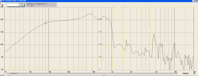
A rough sim of the Faital 8FE200 4 ohm in series hitting Xmax @ 90Hz; 117,5dB with port velocity >17m/s
It looks very promising🙂
How do I inspect the phase response in relation to the cancelation notch. Should I just view the minimum phase at the mid-port?
/Thomas
It looks very promising🙂
How do I inspect the phase response in relation to the cancelation notch. Should I just view the minimum phase at the mid-port?
/Thomas
Attachments
How do I inspect the phase response in relation to the cancelation notch. Should I just view the minimum phase at the mid-port?
/Thomas
Not sure what you are asking. The only phase that I ever concern myself with is what comes out of the mouth. That's the phase that counts.
What if you block off the front of the mid driver, and tap into the horn from the vent hole on back instead. Rip off the dustcap, or maybe something originally intended as coaxial?
Does that let you cram more and bigger mid drivers closer together? Does that let you more easily plug up the cavity and still have a reasonable frustrum?
I'm just saying the back end is usually smaller than the front, especially some of the neodymiums. And you are trying to get maybe 4 of them as close as possible to the central compression driver...
Edge of the ports appears ~5.5cm, center would be a greater distance.
The midrange phase change on the SH-95 would make me guess the acoustical crossover is around 1000 Hz.
My 8" and DH1A are electronically crossed LR24 at 850 and 1000 Hz IIRC, and the phase response looks similar to the DSL SH-95.
If the crossover is around a 1000Hz the mids should tap in at approx. 8.58cm from the acoustic center of the CD to obey the quarter wavelength rule in relation to the cancellation notch.
From the SH-95 pictures, the ports appear to tap in at a greater distance - but then again, looks can be deceiving😛
/Thomas
... From the SH-95 pictures, the ports appear to tap in at a greater distance...
do you measure from (port)hole middle or edge ?
do you measure from (port)hole middle or edge ?
The average area of tap-in (~middle) dictates the crossover.
/Thomas
The average area of tap-in (~middle) dictates the crossover.
I can understand that for any smaller holes
but surely larger oval holes must be different 😕
I would suggest average middle point of the oval hole would be the radius/centre of each end circle of the oval hole
Attachments
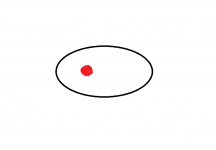
And as seen in your graphic, there would be another red dot on the other end of that oval, therefore the average would be the center of the oval.
that is your choice, and your project
basicly, the problem is that for such a relatively big hole the acoustic centre cannot just be considered like a small point ... it have be considered like a small area
the average distance to 'acoustic centre' is the edge of that area, hence the red dot I suggested
basicly, the problem is that for such a relatively big hole the acoustic centre cannot just be considered like a small point ... it have be considered like a small area
the average distance to 'acoustic centre' is the edge of that area, hence the red dot I suggested
that is your choice, and your project
basicly, the problem is that for such a relatively big hole the acoustic centre cannot just be considered like a small point ... it have be considered like a small area
For the purposes of performing calculations and simulations, using a single point is the most practical approach.
the average distance to 'acoustic centre' is the edge of that area, hence the red dot I suggested
You must also consider the acoustical size of the wave lengths involved. The frequencies that come out of that port are acoustically large compared to the size of the port. If the acoustical center was off to the side like in your red dot graphic, the pressure would be significantly higher at the red dot than the middle of the port. As long as laminar flow is maintained through the port, the acoustic center will be self-centering and follow the path of least resistance. Either way, we might be getting too picky here. What's the difference in length from your red dot graphic and the center of the oval? Probably not enough to make a significant difference.
Either way, we might be getting too picky here. What's the difference in length from your red dot graphic and the center of the oval? Probably not enough to make a significant difference.
when looking at mid port in pics of SH-95, I would guess at something like 2cm or 1" difference in how we look at it
but if using the same when placing the hole, what difference will it make then


If the acoustical center was off to the side like in your red dot graphic, the pressure would be significantly higher at the red dot than the middle of the port. As long as laminar flow is maintained through the port, the acoustic center will be self-centering and follow the path of least resistance.
Thank you John, for revisiting the laws of (fluid) flow. It makes a lot of sense!
/Thomas
Last edited:
- Home
- Loudspeakers
- Multi-Way
- Suitable midrange cone, for bandpass mid in Unity horn