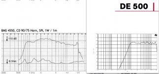
There's a typo in my post. I said that "The BMS 4550 is the only compression driver I've seen that has a 1" exit, yet has response out to 1khz and does not resort to exotic diaphragm materials."
I meant to say "The BMS 4550 is the only compression driver I've seen that has a 1" exit, yet has response out to 20khz and does not resort to exotic diaphragm materials."
I meant to say "The BMS 4550 is the only compression driver I've seen that has a 1" exit, yet has response out to 20khz and does not resort to exotic diaphragm materials."
You have not been looking very hard 😉.I meant to say "The BMS 4550 is the only compression driver I've seen that has a 1" exit, yet has response out to 20khz and does not resort to exotic diaphragm materials."
The titanium diaphragm B&C DE 500 is about 12 dB down at 20 kHz, about the same as the BMS 4550.
It does not have as large of a breakup peak as the BMS 4550, and far more LF.
The upper peaks can be equalized in either case, but you can't EQ out distortion caused by lack of displacement.
That said, either 1" would work fine for a three way Synergy, but the B&C DE 500 could be used crossing over low enough that small mid cones would not be needed, saving driver cost and simplifying construction and crossover details.
Art
Attachments
Weltersys I am seeing maybe a 800hz crossover with the DE500?
I think others have stated the 4550 being used at 900hz cross. I am not sure how using the 500 would help to eliminate the use of mids. I am only asking and not arguing. The DE250 looks very similar to the 500 also. But I am only looking at a small simulation.
I think others have stated the 4550 being used at 900hz cross. I am not sure how using the 500 would help to eliminate the use of mids. I am only asking and not arguing. The DE250 looks very similar to the 500 also. But I am only looking at a small simulation.

Both the horns in post #1406 are not designed to go low, (as you can see in post #1404 the 4550 goes much lower on the conical horn I tested it on) but the 4550 is about -25 at 500 Hz, the 500 about -20 at 500 Hz.Weltersys I am seeing maybe a 800hz crossover with the DE500?
I think others have stated the 4550 being used at 900hz cross. I am not sure how using the 500 would help to eliminate the use of mids. I am only asking and not arguing. The DE250 looks very similar to the 500 also. But I am only looking at a small simulation.
The additional +5 dB and the greater Sd of the B&C DE500 could make upwards of 10 dB difference at a low crossover (around 700-800 Hz), which for home use makes crossing over to a 6" or 8" no problem.
Last edited:
Is it possible to simulate oval ports such as what TD uses?Chrapladm,
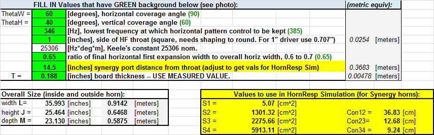
Here is what I managed to come up with for your 15 inch drivers (qnty 2). I ended up putting the bass injection ports at 14.5 in from the throat - you want bass ports to be farther out rather than close in. I had to put a big 3.5 mH coil and fat 8 ohm power resistor to tame the rising response but it is still there - so best to EQ it out rather than burn up precious watts on a resistor. I put this is a 38 in wide x 32 in high x 28 in deep box (3/4 in ply assumed) with qnty 3 x 6.0 in dia x 8 in long bass reflex ports. The bass driver injection ports are 3.0 in diameter.
Here is the input to the spreadsheet:
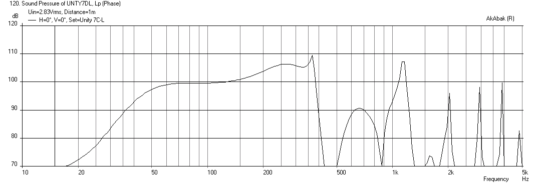
Here is the SPL vs Freq for 2.83V input - pretty sensitive speakers
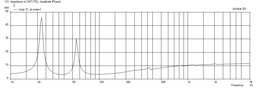
Here is the Impedance curve:
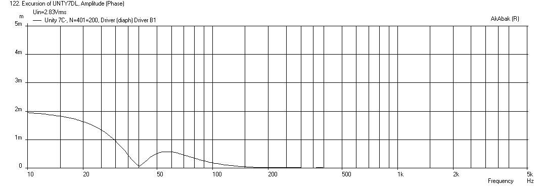
Here is the max cone displacement at 40 volts rms (really needs a high pass filter at 40 Hz):
Here is the corresponding max SPL at max excursion (it will do 122 dB):
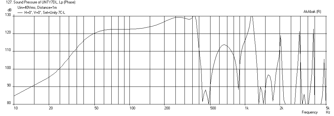
At max SPL, there may be some port noise as the velocities are reaching 20 m/s in the ducts. However, I don't think you can hear that given the 122 dB from the main output.
This design achieves providing a high end up to about 350 Hz so that it can be integrated with a mid driver, it achieves usable bass extension down to about 45 Hz.
What negatives are there when using two ports per woofer for the injection ports?
The rear ports are for extension but I wanted to make sure I stay away from anything close to 20m/s. Not sure what is tolerable but this is all in a horn and I would prefer to keep the chuffing down to nil.
I only ask about the ports because I did not see a screen shot of your simulations on the input page. What was your volume under the cone also used?
I am trying to start off with your simulation and go from there. Not trying to have you sim everything.
Chrapladm,
The shape of the port isn't really accounted for at this level of code in Akabak - it is the cross sectional area that matters. If you had a rather large port, and you actually accounted for the port to act as a radiator in addition to feeding pressure to the horn, then you can specify the dimensions of the port - in this case, a rectangle to approximate a lengthened oval slot.
I modeled the volume behind the port very crudely - I assumed it is a cone with the base of the cone set by the Sd and the height of the cone by a guessed depth (in this case 6 in for a 15 in driver). I also have a 1 inch spacer to provide enough clearance for the surround not to bump under full stroke. You can refine this if you have actual dimensions. It changes things a little - mostly the HF cutoff.
To reduce port velocities, you will need to use larger diameter ports or resort to a rectangular slot or shelf port. Larger diameters will require longer lengths. The velocities should be kept below 10 m/s to minimize chuffing noise. Rounded port entries also reduce noise.
Here is the Akabak script that I used to model the bass horn for you - you can play with the ports.
Good luck!
X:
Code:
| Unity inspired 90 deg x 90 deg horn based on Bwaslo's spreadsheet (v5)
| XRK971  Nov 11, 2013
| Version 7DL is Chrapladm's sim with 15 in woofer

System 'Unity 7DL'

Def_Const
{

| ### input parameters ###

| ### Note that to include room boundary effects, the "Reflection" switch below horn mouth needs to be un-commented
Speaker_pos=48 * 0.0254;  | height above floor or below ceiling (ceiling mount aim down 30 deg)
Dist_wall=5000 * 0.0254;    | distance from back wall

| ## Dimensions of horn from Bwaslo's spreadsheet v5
| These dims are for a 90 deg x 90 deg horn with 385 Hz low freq directivity

S1=6.45 / 10000;   | CSA at CD throat - 1.8cm x 1.8cm (5.06cm2 - round 1 in dia hole or 6.45cm2 - 1 in square throat)
S2=1301 / 10000;    | CSA at location of bass injection - cm^2 (426 cm2)
S3=2276 / 10000;   | CSA at location of diffraction angle change - cm^2 (1565 cm2)
S4=5913 / 10000;   | CSA at horn mouth exit - cm^2 (3704 cm2)
Con12=36.83 / 100; | Dist from CD throat to bass injection port - cm (9.53 cm)
Con23=12.68/ 100;  | Dist from bass injection port to diffraction angle change - cm (9.46 cm)
Con34=9.24 / 100;  | Diat from diffraction angle change to horn mouth radiator - cm (4.41cm)

| ## Calculate horn edge dimensions assuming square

D3=sqrt(S3); | Edge dim of diffraction mouth
D4=sqrt(S4); | Edge dim of mouth exit

| ### Exterior physical size of speaker including board thickness

Width = 38.0 * 0.0254;  | overall width (inches)
Height = 32.0 * 0.0254; | overall height (inches)  increase as needed to provide more vol for sealed enclosure for high Qts drivers
Depth = 28.0 * 0.0254;  | overall depth including allowance for CD body

|  ### Bass driver chambers and throat

Driver_depth=6.0 * 0.0254;  | Depth of cone recess for bass driver (6 inches) (assumed for now)
Driver_spacer=1.0*0.0254;  | Spacer between driver and horn panel to allow surround clearance (assumed for now)

Vol_ch_bass=(930E-4 * Driver_depth)/3 ;     | Driver chamber vol formed by speaker cone in cu meters
L_ch_bass=Driver_depth+Driver_spacer;       | Depth of driver chamber formed by concave cone

S_thr_bass=3.0 * 0.0254;  | Horn bass driver port dia in inches

Wall_thickness=0.75 * 0.0254;   | Thickness of wall material - assumed 0.5 inch plywood
Thk=Wall_thickness;              | abbreviate above

| ### bass reflex vents qnty 3

Vent_dia=8.0*0.0254;
Vent_len=12.0*0.0254;

| ### Rear chamber volume formed from enclosur

V_outer=(Width-2*Thk)*(Height-2*Thk)*(Depth-2*Thk); | External volume of enclosure
V_horn1= 0.33*S3*(Con12+Con23);  | Vol of first horn segment from CD to diffraction edge - vol of pyramid
V_horn2= 0.5*(S3+S4)*Con34;      | Vol of second segment approximated by rough formula for vol of obelisk
V_encl=0.95*(V_outer-V_horn1-V_horn2);    | Total volume of main enclosure * factor for driver magnets and baskets

| ### Note that baffles and bracing (or stuffing) will be required to breakup internal box modes. If L_encl allowed to get large, resonance peaks appear

L_encl=(Depth-2*Thk)/4;  | Longest dim of main chamber with baffles to break up modes (approx < 4 in)

}

Def_Driver  'C15'  | Chrapladm Post in multi-way Nov 8 2013
  SD=930cm2   |  Piston guess for a 15 incher
  fs=39Hz
  Qms=9.30
  Qes=0.39
  Re=5.1ohm
  Le=1.1mH
  Bl=17.6Tm
  Vas=218L


| ### Define speaker position relative to room with horn axis CL at Speaker_pos above floor and Dist_wall away from back wall

Def_Reflector  HorizEdge
Bottom={Speaker_pos}  Top={Dist_wall+Depth}
HAngle=0  VAngle=0

| ### Define driver arrangement

| ### 4 x 4ohm Bass drivers in series/parallel 4 ohms net impedance

| Use EQ or inductor and resistor (like BSC) to tame rising HF response of bass driver, 10 ohms and 2.4mH works for 4 drivers

Resistor    'RBass'  Node=1=350  R=8ohm
Coil    'IBass'  Node=1=350  L=3.0mH  Rs=0.6ohm

Driver Def='C15' 'Driver B1'
Node=350=0=401=200

Driver Def='C15' 'Driver B2'
Node=350=0=402=200

OFF
Driver Def='C15' 'Driver B3'
Node=350=351=403=200

OFF
Driver Def='C15' 'Driver B4'
Node=351=0=404=200

| ### Define bass driver injection chambers
| ### Chamber is connected to main horn via duct to node=12

Enclosure  'Bass Chamber 1'  Node=401
    Vb={Vol_ch_bass}  Qb/fo=1.0  Lb={L_ch_bass}
Duct    'Bass chamber throat1'  Node=401=12
    dD={S_thr_bass}  Len={Wall_thickness}

Enclosure  'Bass Chamber 2'  Node=402
    Vb={Vol_ch_bass}  Qb/fo=1.0  Lb={L_ch_bass}
Duct    'Bass chamber throat2'  Node=402=12
    dD={S_thr_bass}  Len={Wall_thickness}
OFF
Enclosure  'Bass Chamber 3'  Node=403
    Vb={Vol_ch_bass}  Qb/fo=1.0  Lb={L_ch_bass}
OFF
Duct    'Bass chamber throat3'  Node=403=12
    dD={S_thr_bass}  Len={Wall_thickness}
OFF
Enclosure  'Bass Chamber 4'  Node=404
    Vb={Vol_ch_bass}  Qb/fo=1.0  Lb={L_ch_bass}
OFF
Duct    'Bass chamber throat4'  Node=404=12
    dD={S_thr_bass}  Len={Wall_thickness}


| ### Define back chamber, sealed with damping for Qb/fo=0.7, node=200

Enclosure  'Back Chamber Main'  Node=200
    Vb={V_encl}  Qb/fo=0.7  Lb={L_encl}

| ### Rear firing vent for main enclosure

Duct    'Vent_Rear'  Node=200=201
    dD={Vent_dia}  Len={Vent_len}

Radiator  'Rear_Rad'  Def='Vent_Rear'    Node=201
    x=0  y=0  z={-Depth}  HAngle=180  VAngle=0
    WEdge={Width/2}  Hedge={Height/2}
    |Reflection
Label=20

| ### Right firing vent for main enclosure

Duct    'Vent_Right'  Node=200=202
    dD={Vent_dia}  Len={Vent_len}

Radiator  'Right_Rad'  Def='Vent_Right'    Node=202
    x={Width/2}  y=0  z={-Depth/2}  HAngle=90  VAngle=0
    WEdge={Depth/2}  Hedge={Height/2}
    |Reflection
Label=21

| ### Left firing vent for main enclosure

Duct    'Vent_Left'  Node=200=203
    dD={Vent_dia}  Len={Vent_len}

Radiator  'Left_Rad'  Def='Vent_Left'    Node=203
    x={-Width/2}  y=0  z={-Depth/2}  HAngle=-90  VAngle=0
    WEdge={Depth/2}  Hedge={Height/2}
    |Reflection
Label=22

| ### Define horn waveguide geometry using values generated from Bwaslo's spreadsheet

Waveguide 'Horn Seg 1'  | From CD throat to bass injection port at node=12
Node=10=12
    STh={S1}  SMo={S2}
    Len={Con12}  Conical

Waveguide 'Horn Seg 2' | From bass injection port to diffraction angle change
Node=12=13
    STh={S2}  SMo={S3}
    Len={Con23}  Conical

Horn    'Horn Seg 3'  | From diffraction angle change to mouth radiator
Node=13=14
    STh={S3}  WMo={D4}  HMo={D4}
    Len={Con34}  Conical
    Ws={D3}  Hs={D3}
    x=0  y=0  z=0  HAngle=0  VAngle=0
    dEdge={D4}  Label=100
| ### Remove comment bar to include effects of room wall and floor/ceiling
|ReflectionSo the patented shape of the BMS - a ring - is a clever way of having your cake and eating it too. It has the same voice coil diameter as a dome, but the size of the radiator is reduced.
As i understand the Bms patent is for the phase plug and not the ring radiator diaphragm , though the patent paper goes to lengths describing the benefits of the ring radiator when used along with the - phase plug
Fane and many others have used ring radiators over a long period of time
Yes Bms is the first to use the surface area of the radiator + phase plugs earlier designs used just a radial part , fixed with a phasing / wave guide arrangement comoonly refered to as bullet tweeter
Now Faital Pro , Jbl D2 are some of the drivers with Non fancy material diaphragms using the ring radiator in a similar fashion with good success .
The BMS drivers success is in its motor design , the magnet is neo but not N grade as mostly used , when matched to the steel alloy developed and used in their motor structure optimised over the other properties that define a magnet mkakes it a much superior driver / than designed by the fea tools we are using . (BMS refers to this as superior grade Neo Magnets for light weight etc,)
Suranjan
JLH did you ever build a horn and use your Visaton M10's?
I keep hearing bad and good things about them. Makes me nervous as to what I am buying is all. Also curious to see what you came up with.
I keep hearing bad and good things about them. Makes me nervous as to what I am buying is all. Also curious to see what you came up with.
JLH did you ever build a horn and use your Visaton M10's?
I keep hearing bad and good things about them. Makes me nervous as to what I am buying is all. Also curious to see what you came up with.
One of the B&C Speakers DE120 drivers I ordered was defective (open voice coil). Parts Express covered it no questions asked, but B&C is telling them no stock until April 2014. Everything is delayed until then.
That is very disappointing to those of us standing on or looking over your shoulders. Funny though that PE doesn't show it as out of stock; usually they do.
Sorry to hear also. I will have to wait 3 more weeks to get my M10's. Then about late January I should be able to get my CD's. So watching and learning from others gets me by.
So maybe both our projects will be done about the same time. 😀
So maybe both our projects will be done about the same time. 😀
That is very disappointing to those of us standing on or looking over your shoulders. Funny though that PE doesn't show it as out of stock; usually they do.
Yeah, I think they are trying to play the Just-In-Time inventory game with B&C. Although, I've always referred to this as the Just-Too-Late inventory game. 😀
Since my project is stuck on hold I just wanted to drop this script here for you guys to look at. I feel pretty good about it. This will be a 3-way paraline Synergy when I'm done. I have not added the woofers to the script yet. Just have the compression driver and mid with crossovers figured out. I've got plenty of time to figure out which woofers and their crossover.
System 'Paraline_Synergy'
Def_Driver 'CompDriver' | B&C DE120 compression driver
Sd=10.178cm2
Bl=8.2Tm
Cms=3.45E-05m/N
Rms=0.18Ns/m
Fs=1900Hz
Le=0.14mH
Re=7.5ohm
ExpoLe=0.618
Def_Driver 'MidDriver' |Eminence Alpha-6CBMRA 6" mid
Sd=126.7cm2
Bl=7.86Tm
Cms=1.97E-05m/N
Rms=3.29Ns/m
fs=406.98Hz
Le=0.38mH
Re=5.26ohm
ExpoLe=0.618
Def_Const | Unit is cm
{
FcPortMid_Len=0.2e-2; | Mid Enrty Port length
FcPortMid_dD=0.88705e-2; | Mid Entry Port diameter
Rg=0.50; |Amplifier output impedance (ohms)
R1Comp = 39; |compression driver Crossover R1 Resistor (Ohms)
R2Comp = 15; |compression driver Crossover R2 Resistor (Ohms)
R3Comp = 12; |compression driver Crossover R3 Resistor (Ohms)
C1Comp = 8.2e-6; |compression driver Crossover C1 capacitor (Farads)
C2Comp = 27e-6; |compression driver Crossover C2 capacitor (Farads)
C3Comp = 1.0e-6; |compression driver Crossover C3 capacitor (Farads)
L1Comp = 0.68e-3; |compression driver Crossover L1 inductor (Henries)
L2Comp = 0.068e-3; |compression driver Crossover L2 inductor (Henries)
R1Mid = 2.7; |Mid Crossover R1 Resistor (Ohms)
R2Mid = 25; |Mid Crossover R2 Resistor (Ohms)
C1Mid = 27e-6; |Mid Crossover C1 capacitor (Farads)
L1Mid = 1.2e-3; |Mid Crossover L1 inductor (Henries)
S1 = 1.1975e-4; |WG1 throat area & Comp phase plug (sq cm)
S2 = 5.1006e-4; |WG2 mouth area & horn segment 2 throat area & compression driver exit (sq cm)
S3 = 12.3e-4; |WG3 mouth area & horn segment 3 throat area & Mid tap point (sq cm)
S4 = 46.62e-4; |WG4 mouth area & horn segment 4 throat area (sq cm)
S5 = 1881e-4; |WG5 mouth area & horn segment 5 throat area (sq cm)
L12 = 3.9e-2; |WG1 axial length(cm)
L23 = 2.4e-2; |WG2 axial length(cm)
L34 = 9.3e-2; |WG3 axial length(cm)
L45 = 42e-2; |WG4 axial length(cm)
VrcComp = 0.08e-3; |compression driver Rear chamber volume (litres)
LrcComp = 0.84e-2; |compression driver Rear chamber average length (cm)
VtcComp = 0.75e-6; |compression driver Throat chamber volume (cc)
AtcComp = 15.520e-4; |compression driver Throat chamber cross-sectional area (sq cm)
ArcComp = VrcComp / LrcComp; |Conversions for CompDriver
LtcComp = VtcComp / AtcComp;
Sd=126.7E-02;
}
Duct 'CompRearChamber' Node=30=31
SD={ArcComp} Len={LrcComp} Visc=0
Driver 'D1' Def='CompDriver' Node=0=13=31=32
Duct 'CompFrontChamber' Node=32=140
SD={AtcComp} Len={LtcComp} Visc=0
Radiator 'Diaphragm1' Node=100 SD={Sd} Label=1
Driver 'D2' Def='MidDriver' Node=42=0=100=120
Enclosure 'E1' Node=120=130 Vb=116.87cm3 Lb=3.5cm |Mid front chamber volume
Duct 'DuMid_BP1' Node=130=160 dD={FcPortMid_dD} Len={FcPortMid_Len}
Duct 'DuMid_BP2' Node=130=160 dD={FcPortMid_dD} Len={FcPortMid_Len}
Duct 'DuMid_BP3' Node=130=160 dD={FcPortMid_dD} Len={FcPortMid_Len}
Duct 'DuMid_BP4' Node=130=160 dD={FcPortMid_dD} Len={FcPortMid_Len}
Duct 'DuMid_BP5' Node=130=160 dD={FcPortMid_dD} Len={FcPortMid_Len}
Duct 'DuMid_BP6' Node=130=160 dD={FcPortMid_dD} Len={FcPortMid_Len}
Duct 'DuMid_BP7' Node=130=160 dD={FcPortMid_dD} Len={FcPortMid_Len}
Duct 'DuMid_BP8' Node=130=160 dD={FcPortMid_dD} Len={FcPortMid_Len}
Duct 'DuMid_BP9' Node=130=160 dD={FcPortMid_dD} Len={FcPortMid_Len}
Duct 'DuMid_BP10' Node=130=160 dD={FcPortMid_dD} Len={FcPortMid_Len}
Duct 'DuMid_BP11' Node=130=160 dD={FcPortMid_dD} Len={FcPortMid_Len}
Duct 'DuMid_BP12' Node=130=160 dD={FcPortMid_dD} Len={FcPortMid_Len}
Resistor 'Amplifier Rg' |Amplifier output impedance
Node=1=2
R={Rg}
Resistor 'R1Comp'
Node=2=10
R={R1Comp}
Resistor 'R2Comp'
Node=12=13
R={R2Comp}
Resistor 'R3Comp'
Node=13=0
R={R3Comp}
Capacitor 'C1Comp'
Node=2=10
C={C1Comp}
Capacitor 'C2Comp'
Node=10=11
C={C2Comp}
Capacitor 'C3Comp'
Node=12=0
C={C3Comp}
Coil 'L1Comp'
Node=10=0
L={L1Comp}
Rs=0.4ohm
Coil 'L2Comp'
Node=11=12
L={L2Comp}
Rs=0.15ohm
Resistor 'R1Mid'
Node=41=42
R={R1Mid}
Capacitor 'C1Mid'
Node=2=40
C={C1Mid}
Coil 'L1Mid'
Node=40=41
L={L1Mid}
Rs=0.6ohm
Waveguide 'WG1'
Node=140=150
STh={S1}
SMo={S2}
Len={L12}
Conical
Waveguide 'WG2'
Node=150=160
STh={S2}
SMo={S3}
Len={L23}
T=1
Waveguide 'WG3'
Node=160=170
STh={S3}
SMo={S4}
Len={L34}
Conical
Waveguide 'WG4'
Node=170=180
STh={S4}
SMo={S5}
Len={L45}
Conical
Radiator 'Horn mouth'
Node=180
SD={S5}
x=0
y=0
z=0
HAngle=0
VAngle=0
Last edited:
basic questions about akabak
Thanks, JHL. I'm looking at your script while I'm learning Akabak so I have a couple of basic questions.
Exporting a script from a HornResp. I was surprised to see that the HornResp SPL matched the Akabak acoustic power graph. Researching HornResp help, I found that HornResp assumes constant directivity and "the constant directivity SPL respsonse is the acoustic power response". I suppose I should have known that. I see then why one needs to move from HornResp to Akabak. (is the following correct?) HR gives you the general shape of the response and puts the peaks and nulls in the right places but its exported SPL shouldn't be used to develop a crossover (which I had just done😱)
You've explained in other posts that the rising response seen in the SPL simulation is compensated by the falling response of the CD horns being simulated but not why the simulations don't take that into account. Can you explain why the simulations don't or can't take that into account so that the target SPL would be flat?.
Thanks.
Jack
In Akabak the acoustical pressure graph shows you the rising response in the model. The Acoustical power graph shows the response with the horn's CD taken in consideration.
so I had it backwards, the HornResp output is fine so long as I'm modeling a CD horn. I just can't get as detailed in HR.
I see the Paraline in your script. S2- S4 expand slowly. That must be it. S4-S5 looks like a conventional conical segment. You appear to be doing the mount the mid over the CD trick with all those ducts from the mids front chamber down into the WG at the tap point. Now we know why you wanted such a small CD...
I see the Paraline in your script. S2- S4 expand slowly. That must be it. S4-S5 looks like a conventional conical segment. You appear to be doing the mount the mid over the CD trick with all those ducts from the mids front chamber down into the WG at the tap point. Now we know why you wanted such a small CD...
btw
regarding one pair of bigger mids, sidemounted
it seems to me like they are easy to get very closer to the throat than multiple smaller drivers 😕
regarding one pair of bigger mids, sidemounted
it seems to me like they are easy to get very closer to the throat than multiple smaller drivers 😕
I thought the problem with using large mids was trying to keep velocity in check. Smaller mids is easier. But I could be wrong.
yeah, you are probably right about that
needs bigger ports (lower xo point)
bigger tweeter that can be crossed lowish
(thinking about trying the low compression BMS4555)
and, there might be a serious problem having bigger port holes very close to tweeter throat
it's always like a can of worms
I'm not interested because I think it makes sense
just curious to hear how it works, and it might be fun
and ... I only need to build one, for my bass guitar 😀
- Home
- Loudspeakers
- Multi-Way
- Suitable midrange cone, for bandpass mid in Unity horn