Looks like the mid ports for the DSL SH95 8 inch speaker start within around 5.5 cm of the throat, but drawing out the specific drivers one plans to use is important.How do you plan to get the mids within 5.5cm of the throat? Try drawing the actual horn out with the drivers you plan to use and tell me if it can be physically built.
Attachments

You're not simulating it correctly. I had this problem too until I figured it out.
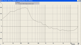
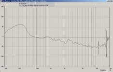
First, plot the vector response of the phase. In this case it's called "Amplitude (Phase)" in the drop-down. Once it plots the new graph, go to the top menu and select "Calc" --> "minimum phase". The node to look at is the horn mouth. This will give you the real unwrapped phase of the system.
John!
I'm fiddling with your old Tri_Unity script, I just can't seem to get the same phase response as you. I believe it's the same script😕
The first phase plot is taken from post #163. The second plot is the one I ran with the Tri_Unity script.
Is there an explanation to this phase difference?
/Thomas
Attachments

How do you plan to get the mids within 5.5cm of the throat? Try drawing the actual horn out with the drivers you plan to use and tell me if it can be physically built. I ask this only because I've simulated a lot of very nice horns to only find out I couldn't build what I simulated.
I thought the holes have to be close to the mouth, so the edge of a speaker will be close to that, but you are right, if I want a synergy who go as low as 100 hz, I need a three way version, for the mid, a 4 inch one is need or even smaller when using in a home environment because of less need of spl? but more high end sound coming out? I do not need 4 small speakers, I have enough as I use 2 mids and 2 mid bass and one compression driver?
I see that I did look wrong on the danley site that the two way do not go lower then say 350 Hz, a three way with small mids and then the phillips doing bass or other 8 inch woofers..
Last edited:
John!
I'm fiddling with your old Tri_Unity script, I just can't seem to get the same phase response as you. I believe it's the same script😕
The first phase plot is taken from post #163. The second plot is the one I ran with the Tri_Unity script.
Is there an explanation to this phase difference?
/Thomas
Make sure the node you are looking at is the horn mouth.
if only small coaxes were built like high output mids, instead of trying to play bass 🙁
B&C 6FHX51 6.5" Professional Coaxial Speaker 70° x 70° 8 Ohm 294-5761
With Fs of 85 and accordion surround, don't think they were after bass. Then again, don't know if that central flare is convenience or nuisance. Does it perhaps come loose with those two bolts in the photo? If so, you might be able to play with the shape and blend it into a unity...
I had noted a similar 5" earlier. But as you complain: it's Fs 61 and roll surround like they were going for bass. Rediculous in a 5" with 3mm... Assuming we close this up to get some sensitivity in mids, surround is still a roll and no easy fix...
Last edited:
Make sure the node you are looking at is the horn mouth.
If you look at the label of the 2. plot, it says mouth!
That's what I don't understand.
/Thomas
John, would you do me a favor and run the Tri_Unity script you published. This way I'll know if I'm doing something wrong?
/Thomas
/Thomas
Hi All
I see a lot synergy with four mids and four bass mid drivers, but can i do also two mid and two mid bass? and what is the different I will see.
I have in hornresp make the back chamber as big as the mid back chamber who i do make myself so I can simulate but I do not now what happens with Fs, I have to make the chamber and then measure the parameters and then input that on hornresp, is that a better way? The surround of a speaker, the soft ones are to fragile I did hear, I have now use rubber surounds, but the old stiff harmonica form is best?
The unitys have a flare at the end, why is this done? I have seen with simulating that this affect respons.
to learn, i have to experiment right?
regards
kees
Last edited:
Hi All
I see a lot synergy with four mids and four bass mid drivers, but can i do also two mid and two mid bass? and what is the different I will see.
Almost a decade ago, when Danley was at SPL and was discussing the design of the Unity and his basshorns, he talked about the concept of basically segmenting a driver.
For instance, let's say I'm perusing the parts express catalog, and I'm trying to find a woofer with the correct specs for horn loading. I want a driver where 2 * FS / QES = 500hz, to maximize the efficiency in the two octaves from 250hz to 1000hz.

Alpha 6A fits the bill fairly well. It works out at 393hz, it costs $45, it has a 1.5" voice coil and a displacement of 44 square centimeters.

But what if I did something bizarre, like used a 2" driver intended for computer speakers? It works out to 864hz, it costs $21, it has a 0.8" voice coil and a displacement of .13 square centimeters.
Once the light bulb went off over my head, that you could take one driver and slice and dice it into as many segments as you wanted, that really helped a lot. Those little Tangband woofers don't sound like much on a flat baffle, but when you horn load four of them you actually have an array of voice coils with a greater area than a prosound midrange. (This is the same reason that I use arrays of Alpine car subs in my tapped horns instead of the prosound drivers that most people use.)
Besides the advantages in size and packaging, an array of very small drivers also allows you to push the crossover to the compression driver to a higher frequency. And in my experience with Unity horns, I generally find that the weak link in the design is the octave from 1000hz to 2000hz; anything you can do to push the midrange higher can solve a lot of problems. (IE it's better to push the midrange UP in frequency than to push the tweeter DOWN in frequency.)
I have in hornresp make the back chamber as big as the mid back chamber who i do make myself so I can simulate but I do not now what happens with Fs, I have to make the chamber and then measure the parameters and then input that on hornresp, is that a better way? The surround of a speaker, the soft ones are to fragile I did hear, I have now use rubber surounds, but the old stiff harmonica form is best?
The unitys have a flare at the end, why is this done? I have seen with simulating that this affect respons.
to learn, i have to experiment right?
regards
kees
The way that I figure out the volume of the back chamber is to model it as if it was a sealed box. For instance, I would set the back chamber to one liter, and then look at the impedance curve to figure out what the Fb of the box is. Once the Fb is where I want it - about 500hz in the Lambda Unity horn - I would then 'fix' that back chamber size.
Note that sealing off these stupid drivers is a complete p.i.t.a., and in the real world it is sometimes impossible to get the Fb as high as you need it to be. Using a driver that is already sealed off saves a LOT of headaches. On the downside, relegating yourself to drivers that are already sealed off basically eliminates 99% of the loudspeakers that are available unfortunately.
As for the flare in the last few inches of the horn, that smooths out the frequency response, makes a horn sound better by reducing diffraction and reflection from the mouth, and also improves imaging.
Check out 'what's so sacred about exponential horns' by DB Keele and also check out the measurements in my 'Homster' thread where I show the effect of a roundover on a horn
Jack Buska over at audioheritage published some measurements of the effect on tractrix horns also
If you look at the label of the 2. plot, it says mouth!
That's what I don't understand.
/Thomas
I looked and I no longer have that script. The only way to explain it is your script is different somehow.
Hi Patric
Vry much thanks about your technical explaining, Now I have some clue what to do.
Very neat about the tapped horns where you use more little drivers in stead of a big one, I have heard more about it, also smaller drivers are more rigid also and distortion can go down, I will consider it to test that some day.
I need not a synery who has to do big spl, it is used in a home together with a tapped horn, in first glance I did want use a fostex horn with a tapped sub, but I do really like the synergy because of better matching everything, and the sound is very good and dynamic.
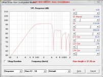
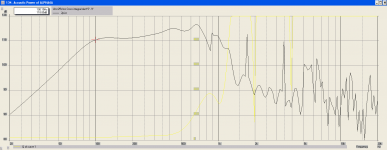
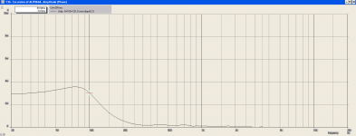
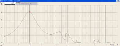
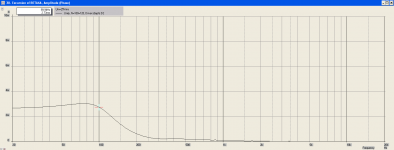
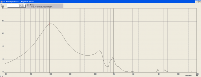
In hornresp i do make first the bass mid part and then the mid keeping horn the same and just move the mid speaker to 4,5 cm from troat, then I get what you see on pictures, with a Phillips old woofer 8 inch and the visaton frs 8m with rubber surround and strong motor..
You are right about why to use a very small mid speaker, I have try it and get more close to 2 Khz when use a 2 inch mid speaker, I presume that using 4 is better then using two? or do I have only less spl for the watts and more cone movement. As you see on the pictures the mid has more spl then the mid, this is always to correct, the other way on it is not except if active amps, but you now that already..
Thanks again for your help.
regards kees
Vry much thanks about your technical explaining, Now I have some clue what to do.
Very neat about the tapped horns where you use more little drivers in stead of a big one, I have heard more about it, also smaller drivers are more rigid also and distortion can go down, I will consider it to test that some day.
I need not a synery who has to do big spl, it is used in a home together with a tapped horn, in first glance I did want use a fostex horn with a tapped sub, but I do really like the synergy because of better matching everything, and the sound is very good and dynamic.
In hornresp i do make first the bass mid part and then the mid keeping horn the same and just move the mid speaker to 4,5 cm from troat, then I get what you see on pictures, with a Phillips old woofer 8 inch and the visaton frs 8m with rubber surround and strong motor..
You are right about why to use a very small mid speaker, I have try it and get more close to 2 Khz when use a 2 inch mid speaker, I presume that using 4 is better then using two? or do I have only less spl for the watts and more cone movement. As you see on the pictures the mid has more spl then the mid, this is always to correct, the other way on it is not except if active amps, but you now that already..
Thanks again for your help.
regards kees
Attachments
Last edited:
with small fullrange drivers instead of compression tweeter, presented this idea before, but was not well received, just so that you are warned, it may not workI need not a synery who has to do big spl, it is used in a home together with a tapped horn, in first glance I did want use a fostex horn with a tapped sub, but I do really like the synergy because of better matching everything, and the sound is very good and dynamic.
Attachments
John, would you do me a favor and run the Tri_Unity script you published. This way I'll know if I'm doing something wrong?
/Thomas
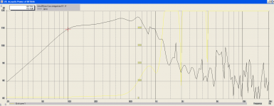
Okay, I ended up finding the script on one of my older lap tops. Here is the script and the attached screen shot. Do take notice that the woofers are not being used in the simulation. They are inactive because of the " | " in front of the line code. The inactive code has been marked in purple to make it clear.
Code:
System 'Tri_Unity'
Def_Driver 'CompDriver' | BMS 4555 compression driver
Sd=15.51cm2
Bl=8.0Tm
Cms=3.45E-05m/N
Rms=0.4Ns/m
Fs=1000Hz
Le=0.12mH
Re=12.5ohm
ExpoLe=0.618

Def_Driver 'MidDriver' |Eminence LA6-CBMR 6" mid
Sd=129.05cm2
Bl=10.10Tm
Cms=1.6E-05m/N
Rms=3.40Ns/m
fs=454.92Hz
Le=0.365mH
Re=6.21ohm
ExpoLe=0.618

Def_Driver 'WoofDriver' |Eminence Delta-10A 10" Woofer
Sd=344.9cm2
Bl=14.4Tm
Cms=1.80E-04m/N
Rms=2.05Ns/m
fs=66Hz
Le=0.74mH
Re=5.42ohm
ExpoLe=0.618

Def_Const | Unit is cm
{
FcMid_Len=1.5e-2; | Front Mid chamber length
FcMid_dD=12.818e-2; | Front Mid chamber diameter
FcPortMid_Len=1.0e-2; | Mid Enrty Port length
FcPortMid_dD=1.8e-2; | Mid Entry Port diameter

FcWoof_Len=4.5e-2; | Front Woofer chamber length
FcWoof_dD=20.9556e-2; | Front Woofer chamber diameter
FcPortWoof_Len=0.3175e-2; | Woofer Entry Port length
FcPortWoof_dD=4.435e-2; | Woofer Entry Port diameter

BrPortWoof_dD=5.35e-2; |Bass Reflex Port diameter
BrPortWoof_Len=14e-2; |Bass Reflex Port length

Rg=2.0;  |Amplifier output impedance (ohms)

R1Comp = 39; |Compression driver Crossover R1 resistance (ohms)
R2Comp = 25; |Compression driver Crossover R2 resistance (ohms)
R3Comp = 8.2; |Compression driver Crossover R3 resistance (ohms)

C1Comp = 5.6e-6; |Compression driver Crossover C1 capacitor (Farads)
C2Comp = 1.0e-6; |Compression driver Crossover C2 capacitor (Farads)
C3Comp = .33e-6; |Compression driver Crossover C1 capacitor (Farads)
C4Comp = 22e-6; |Compression driver Crossover C2 capacitor (Farads)

L1Comp = 1.8e-3; |Compression driver Crossover L1 inductor (Henries)
L2Comp = 0.033e-3; |Compression driver Crossover L1 inductor (Henries)

C1Mid = 45e-6; |Mid Driver Crossover C1 capacitor (Farads)

R1Mid = 20; |Mid Driver Crossover R1 resistance (ohms)
R2Mid = 5.6; |Mid Driver Crossover R2 resistance (ohms)

L1Mid = 3.3e-3; |Mid Driver Crossover L1 inductor (Henries)


S1  = 1.552e-4; |WG1 throat area & Comp phase plug(sq cm)
S2  = 11.37e-4; |WG2 mouth area & horn segment 2 throat area & compression driver exit(sq cm)
S3  = 22.74e-4; |WG3 mouth area & horn segment 3 throat area & Mid tap point(sq cm)
S4  = 93.46e-4; |WG4 mouth area & horn segment 4 throat area & Woofer tap point(sq cm)
S5  = 519.24e-4; |mouth flare out
S6  = 1038.49e-4; |mt

L12  = 7.0e-2; |WG1 axial length(cm)
L23  = 2.27e-2; |WG2 axial length(cm)
L34  = 5.35e-2; |WG3 axial length(cm)
L45  = 15.32e-2; |mouth flare
L56  = 3.78e-2; |mt

VrcComp = 0.08e-3; |compression driver Rear chamber volume (litres)
LrcComp = 0.84e-2; |compression driver Rear chamber average length (cm)
VtcComp = 0.75e-6; |compression driver Throat chamber volume (cc)
AtcComp = 15.520e-4; |compression driver Throat chamber cross-sectional area (sq cm)

ArcComp = VrcComp / LrcComp; |Conversions for CompDriver
LtcComp = VtcComp / AtcComp;
Sd=129.05E-02;
}
Duct 'CompRearChamber' Node=30=31

SD={ArcComp} Len={LrcComp} Visc=0

Driver 'D1' Def='CompDriver' Node=0=11=31=32

Duct 'CompFrontChamber' Node=32=140

SD={AtcComp} Len={LtcComp} Visc=0

Radiator 'Diaphragm1' Node=100 SD={Sd} Label=1
Radiator 'Diaphragm2' Node=101 SD={Sd} Label=2

Driver 'D2' Def='MidDriver' Node=41=42=100=120
Driver 'D3' Def='MidDriver' Node=42=0=101=121

Duct 'DuMid_Fc1' Node=120=130 dD={FcMid_dD} Len={FcMid_Len}
Duct 'DuMid_Fc2' Node=121=131 dD={FcMid_dD} Len={FcMid_Len}

Duct 'DuMid_BP1a' Node=130=170 dD={FcPortMid_dD} Len={FcPortMid_Len}
Duct 'DuMid_BP2a' Node=131=170 dD={FcPortMid_dD} Len={FcPortMid_Len}
Duct 'DuMid_BP1b' Node=130=170 dD={FcPortMid_dD} Len={FcPortMid_Len}
Duct 'DuMid_BP2b' Node=131=170 dD={FcPortMid_dD} Len={FcPortMid_Len}

[COLOR="DarkOrchid"]|Enclosure 'E4' Node=200 Vb=9.5L Lb=12cm
|Enclosure 'E5' Node=201 Vb=9.5L Lb=12cm

|Driver 'D5' Def='WoofDriver' Node=0=2=200=220
|Driver 'D6' Def='WoofDriver' Node=0=2=201=221

|Duct 'DuWoof_Fc1' Node=220=230 dD={FcWoof_dD} Len={FcWoof_Len}
|Duct 'DuWoof_Fc2' Node=221=231 dD={FcWoof_dD} Len={FcWoof_Len}

|Duct 'DuWoof_BP1a' Node=230=170 dD={FcPortWoof_dD} Len={FcPortWoof_Len}
|Duct 'DuWoof_BP2a' Node=231=170 dD={FcPortWoof_dD} Len={FcPortWoof_Len}

|Duct 'DuWoof_BP1b' Node=230=170 dD={FcPortWoof_dD} Len={FcPortWoof_Len}
|Duct 'DuWoof_BP2b' Node=231=170 dD={FcPortWoof_dD} Len={FcPortWoof_Len}

|Duct 'DuWoof_BR1' Node=200=180 dD={BrPortWoof_dD} Len={BrPortWoof_Len}
|Duct 'DuWoof_BR2' Node=201=180 dD={BrPortWoof_dD} Len={BrPortWoof_Len} [/COLOR]

Resistor 'Amplifier Rg'  |Amplifier output impedance
Node=1=2
R={Rg}

Resistor 'R1Comp'
Node=2=10
R={R1Comp}

Capacitor 'C1Comp'
Node=2=10
C={C1Comp}

Capacitor 'C2Comp'
Node=11=0
C={C2Comp}

Coil 'L1Comp'
Node=10=0
L={L1Comp}

Coil 'L2Comp'
Node=10=11
L={L2Comp}

Resistor 'R1Mid'
Node=2=0
R={R1Mid}

Coil 'L1Mid'
Node=2=41
L={L1Mid}

Waveguide 'WG1'
    Node=140=150
    STh={S1}
    SMo={S2}
    Len={L12}
    Conical

Waveguide 'WG2'
    Node=150=160
    STh={S2}
    SMo={S3}
    Len={L23}
    T=1

Waveguide 'WG3'
    Node=160=170
    STh={S3}
    SMo={S4}
    Len={L34}
    Conical

Waveguide 'WG4'
    Node=170=180
    STh={S4}
    SMo={S5}
    Len={L45}
    Conical

Waveguide 'WG5'
    Node=180=190
    STh={S5}
    SMo={S6}
    Len={L56}
    Conical

Radiator 'Horn mouth'
    Node=190
    SD={S6}
    x=0
    y=0
    z=0
    HAngle=0
    VAngle=0
Attachments
with small fullrange drivers instead of compression tweeter, presented this idea before, but was not well received, just so that you are warned, it may not work
That is the beauty if science sometimes it won,t work.
But in the pictures, left is two fullrange and left is one fullrange on place of the compression driver? and can I use two midranges on the sides of the horn? and two bassmid are already used, so i think two mids will work.
Then I keep three way filtering. There are compression drivers who are very hifi others are only for loud PA.
Can hornresp also simulate high frequenties like tweeter specs of do I need akabak for this, I go play with it using
the script from this threat, it is easely to change this I now but write a whole script is not yet possible, need more learning for akabak.
regards
kees
Last edited:
Okay, I ended up finding the script on one of my older lap tops. Here is the script and the attached screen shot. Do take notice that the woofers are not being used in the simulation. They are inactive because of the " | " in front of the line code. The inactive code has been marked in purple to make it clear.
- Snip...
System 'Tri_Unity'
Def_Driver 'CompDriver' | BMS 4555 compression driver
Sd=15.51cm2
Bl=8.0Tm
Cms=3.45E-05m/N
Rms=0.4Ns/m
Fs=1000Hz
Le=0.12mH
Re=12.5ohm
ExpoLe=0.618
Def_Driver 'MidDriver' |Eminence LA6-CBMR 6" mid
Sd=129.05cm2
Bl=10.10Tm
Cms=1.6E-05m/N
Rms=3.40Ns/m
fs=454.92Hz
Le=0.365mH
Re=6.21ohm
ExpoLe=0.618
...-Snap!
I must have altered the original script somehow. I can use this one for comparison.
Thank you, John!
/Thomas
Last edited:
A Synergy with a pair of Alpha 6A (or 8A) and HF driver would allow a crossover point of around 100 Hz to the 18" woofer, which means the woofer placement is not very critical, as it would be if you were using it up to 500 Hz.
If you want to spend more money there are better B&C cones.
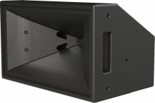
For bass use making the 2 way Synergy wedge shape like the DSL SH-90 (which uses 2 x8" and a 1") would be a good move.
You could do removeable BR port covers for use with or without the sub.
Art!
I'm actually working on a model with the Alpha 6A (sealed box Synergy). It looks very promising using four drivers, adding needed gain to the low end. The Alphas' diaphram displacement is kept just below x-max (3.0mm @ 100Hz hitting 119dB) with the port velocity below 17m/s, port size ø3.15cm. I'm hoping that the port size won't mess up the high frequency with carefull port geometry and placement!
I've modeled the Beta 6A as well. It drops of a tad faster towards the low end, but it has higher power handling and x-max (4.5mm). Furthermore, it shows better roll-off characteristics in the top end, making it easier on the crossover.
Maybe the Beta is the better choice, though it adds $10 a piece, or what do you think?
Note: The frequency range I'm working on is 100-700Hz.
/Thomas
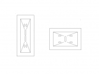
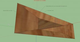
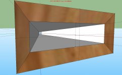
I did a export with hornresp, but in sketchup and with use off push pull I do not get the angles right, but it do go very strange when try to push pull it making open corners and not a nice closed angle, yeahh it is difficult to explane, my technical english is not so well.
Ohh yeah, it is a test from a simulation, so don,t get to serieus about it, i did let see what I get when export through hornresp, the last flare hornresp make a error, or better, hornresp is not made to do that, I have write david about it, maybe he find it interesting to implement.
regards
kees
Ohh yeah, it is a test from a simulation, so don,t get to serieus about it, i did let see what I get when export through hornresp, the last flare hornresp make a error, or better, hornresp is not made to do that, I have write david about it, maybe he find it interesting to implement.
regards
kees
Attachments

Last edited:
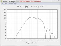
Thomas,Art!
The (four) Alphas' diaphram displacement is kept just below x-max (3.0mm @ 100Hz hitting 119dB) with the port velocity below 17m/s, port size ø3.15cm. I'm hoping that the port size won't mess up the high frequency with carefull port geometry and placement!
I've modeled the Beta 6A as well. It drops of a tad faster towards the low end, but it has higher power handling and x-max (4.5mm). Furthermore, it shows better roll-off characteristics in the top end, making it easier on the crossover.
Maybe the Beta is the better choice, though it adds $10 a piece, or what do you think?
Note: The frequency range I'm working on is 100-700Hz.
What is your reason for designing for sealed rather than bass reflex?
Granted the LF phase response for sealed is smoother, but you have twice the throat port holes and drivers for the same LF output.
I have had experience comparing the Alpha and Beta 8 in my sealed two way Paraline cabinets (eights run 100-850 Hz, sixes could go higher), seemed the reduced LF meant that more power was needed, so the end result was similar, didn't seem worth the additional speaker and amplifier $$.
If you post your Alpha 6/Beta 6 simulations I could give a more informed opinion between the two.
Art
Thank you for your input, Art.
The reason I'm going sealed is that I have the impression that this alignment shows better transient behavior than relflex, or am I missing something? - You also mentioned the phase response.
The simulations are made by aid of the Bill walso Synergy spreadsheet, 60 x 40, 160Hz mouth.
Note: I'm employing DEQX duties in a 3-way active system: Synergy >~100Hz + subs below
/Thomas
Attachments
Last edited:
- Home
- Loudspeakers
- Multi-Way
- Suitable midrange cone, for bandpass mid in Unity horn