I have some sims I did with Hornresp that illustrate this and I'll post them soon. The difference is dramatic; going from a 60x60 horn to a 90x90 horn lowers the output of the compression driver by as much as 10dB at the xover point, a massive difference when we're struggling to get the midranges and the compression driver to play nice with each other.
That is one reason why I really like 60X40 horns. Good room coverage without floor or ceiling bounce issues. In addition, it models and works really well with a number of compression drivers and mids.
DSL offers Synergy horns to fit a variety of coverage applications, the newer models such as the SM-96 (90 x 60) being wider dispersion than the older models, SH-50 (50 x50) and SH-25 (25 x 25).For literally years I thought the reason that Danley was going with narrower and narrower angles was due to the local flare rate.
At this point, I don't think that's the case. Based on some sims I ran, I believe that Danley is going with narrower wall angles because it raises the output level of the compression driver at the xover point.
The obvious problem with a narrow dispersion horn is the depth requires for pattern control down low, the SH-25 is 50.7 inches deep.
Narrower coverage angles are more sensitive, no surprise there, my Maltese conical horns at about 11 x 11 degrees are around 115 dB one watt one meter mid band, but at around 30 inch deep with driver, only have 11 degree pattern control to around 1500 Hz.
Last edited:
Long story short - I would argue that the midrange taps shouldn't be any closer than 10cm away from the throat. And that any further than 15-20cm will likely lead to a secondary problem, which is a reflection off of the throat.
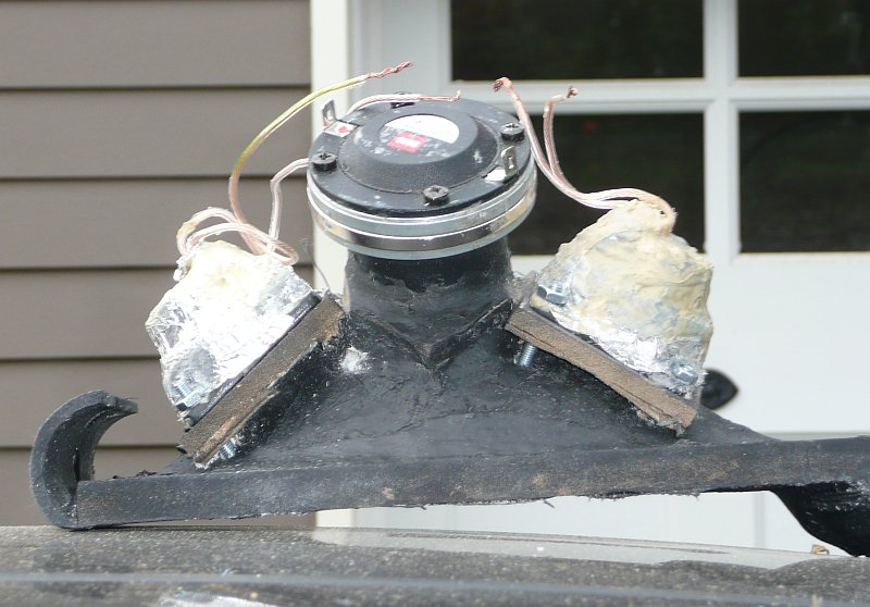
Hmmm, my unity horns made my Danley have the holes approximately 7cm from the bug screen and features 5" Miscos. Where are you defining the measurement from the throat? At the inner most of the throat or the bug screen? 😕
I'm going to drill several fustrums at different lengths and measure each one individually. 10-20cm is a huge guestimate, especially as my unities have a shorter distance (7cm) with a larger driver (5") than I plan to use (3").
Just a thought as the quest for replicating Tom's great design continues. If it is important to define the origin of the compression driver maybe it is desirable do do the same for the mid range. The origin of the latter is not the centre of the cutout in the horn side as it must be the other side of a cylindrical tunnel and a compression chamber in series i.e. a few cm further back. Should be possible to allow for this in Akabak. Experimenting for best measuring audio will account for this anyway but it might be desirable to make the allowance for better theoretical predictions via Akabak etc.
Hmmm, my unity horns made my Danley have the holes approximately 7cm from the bug screen and features 5" Miscos. Where are you defining the measurement from the throat? At the inner most of the throat or the bug screen? 😕
I'm going to drill several fustrums at different lengths and measure each one individually. 10-20cm is a huge guestimate, especially as my unities have a shorter distance (7cm) with a larger driver (5") than I plan to use (3").
We could probably measure the distance from the midrange throats to the compression driver throats using the photos that have been published. If you know the dimensions of the horn and you have a photo of it, you can measure the distance using the photo with Photoshop, Gimp, or Irfanview.
If the midrange throat is too close to the tweeter throat you're going to get interference from one to the other; the further apart they are the more they 'get out of each other's way.'
But it's true that it's difficult to determine where the throat of the tweeter is, because the tweeter throat actually varies with frequency!
For instance, the origin of 10khz is basically way up at the diaphragm of the tweeter. But the origin of the 900hz is at the point where the diameter of the horn measures 9.3cm x 9.3cm.
In a 50 x 50 conical horn with a 2.5cm throat, that point is 10cm down the length of the throat.
Perhaps that's part of it too? Perhaps one varies the wall angle so that the midrange throat is located so that the origin of sound at the crossover point is where the midrange throat is. Or conversely, you can 'fix' the angle of the walls and vary the xover point so that the xover point corresponds to where the origin of sound is at the xover point.
Does that make sense?
I do not think it's as simple as picking a wall angle that suits your needs; the location of the midrange throats is *tied* to the area where the midrange throat is located, and therefore, some wall angles do not work. (IE, good luck getting a Synergy horn to work with a wall angle of 135 degrees, unless you use very very small midranges.)
Also, this is all 'fractal' in nature; the location of the woofer throats is tied to the xover to the woofers to the mids, just as the location of the midrange throats is tied to the location of the tweeter throats. All of these rules apply to all of the drivers, but it's a lot trickier in the high frequencies because a centimeter or two makes a difference, due to the short wavelengths.
Last edited:
DSL offers Synergy horns to fit a variety of coverage applications, the newer models such as the SM-96 (90 x 60) being wider dispersion than the older models, SH-50 (50 x50) and SH-25 (25 x 25).
The obvious problem with a narrow dispersion horn is the depth requires for pattern control down low, the SH-25 is 50.7 inches deep.
Narrower coverage angles are more sensitive, no surprise there, my Maltese conical horns at about 11 x 11 degrees are around 115 dB one watt one meter mid band, but at around 30 inch deep with driver, only have 11 degree pattern control to around 1500 Hz.

I'd argue that wider coverage angles are harder. Getting a 90x90 Synergy horn to work would be tough. My first Unity horn was 108 degrees x 72 degrees; if only I knew then what I know now 🙂
To get a wide angle to work I'd need a really low xover point, very very small midranges, or both. In my opinion, this is why Danley opted for a BMS coax at the apex of that SM-96. (The 5" BMS coax, to be specific.)
The SH-96 may use a coax too; it has a 1.4" throat and eleven drivers on the horn. Bit of a brute force approach, but I'd lover to hear it! Is that the one that's in the Imax in Chicago?
You do seem to like to argue.I'd argue that wider coverage angles are harder. Getting a 90x90 Synergy horn to work would be tough.
The 100 x 100 degree SH-100 works well, though not as smooth as most of the others.
It is the simplest from a driver standpoint, a single 8" co-ax.
As in all Synergy horns, the crossover is a key element, the part that is the most "tough" to get right.
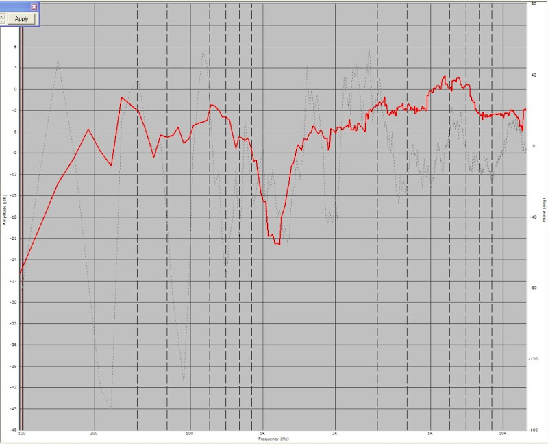
The 20 dB hole in the response around 1200 Hz in your post #730 looks like a crossover problem.
Whenever possible I try to qualify my opinions, and that's the reason I often use terms like "IMHO" and "I would argue"
I've been wrong about a LOT of things when it comes to these devices, and I'm often throwing information out there to get feedback from the community.
My most successful project have been clones of the Danley devices; for instance my TH-Mini 'clone' is the best sub I own.
At the same time, I need more speakers like I need another hold in my head, and 90% of the reason I embark on these projects is to figure them out. (If I had Jay Leno money I would have a garage full of speakers and bicycles instead of a garage full of exotic cars.)
Basically if I simply needed a Unity horn I'd build the Lambda Unity horn, Cowan has published everything you need to build one. But the fun part for me is reverse-engineering things.
If the midrange throat is too close to the tweeter throat you're going to get interference from one to the other; the further apart they are the more they 'get out of each other's way.'
Loddie's measurements of the Lambda Unity are correct. With my slightly modified version (ala: http://www.diyaudio.com/forums/multi-way/17642-first-pics-new-speaks-2.html#post628572 ), there is little passive interference. Or at least the effects don't show up in the in the raw response profiles. I found that I could measure the tweeter (TAD 2001) with or without the mid ports taped over, and the measurements would be identical. Same, if I measured the mids (Misco) with the tweeter entry physically blocked. That doesn't rule out audible reflections that might show up on a waterfall plot. I do use the reticulated foam for about half the depth of the WG.
Sheldon

Interesting, I wasn't aware of this. Does this predate John Sheerin's? Also, why was everyone that cloned a Unity named "John?" (My real name is John 😛 )
Unity vs Uno - hancock - High Efficiency Speaker Asylum
" this week I went to listen to some Avant Garde Unos to compare to my Unitys...every so often it's useful to callibrate to an external reference to see if you're on the right track. I am definitely on the right track. I know there is a tendency to be biased towards something your own project, but it wasn't even close. One caveat--I am doing DSP equalization on my system, which does make a dramatic difference to just about any system. However, the Unity is an ideal system for doing DSP since it is truly a point source. On the Unity, when you equalize the on-axis response, you also equalize the off-axis response. With the Avant Garde the drivers are separated by a large amount physically and with the widely varying power response, I don't think DSP would help that much. You might be able to get one point in spafce sounding absolutely glorious, but you'd have to lock your head in a vice to appreciate it and your friends would be sol.
Somebody else mentioned the problems of mating a monopole bass to horn mids and treble and I heartily agree. I was reminded of my first Unity setup with monopole bass. Now it's dipole and there's no going back--until I have the room to try out my plane-wave/active-echo-cancellation bass idea.
John"

On page 73 I posted some data to illustrate where the midrange taps should go. In that post, I argued that the ideal tap is somewhere between 10cm and 20cm. Additionally, I argued that getting the mids too close to the throat will cause interference with the tweeter.
Also, I believe that narrow angle Unity horns are easier to implement than wide angle Unity horns, and that's it's borderline impossible to get a wide angle Unity horn to work UNLESS you use very small midranges, a very large tweeter, or both. (The Danley SM-96, with a coverage angle of 60x90, uses a coaxial driver at the apex, which gets the mids very close to the compression driver.)
So let's explore these hypotheses.
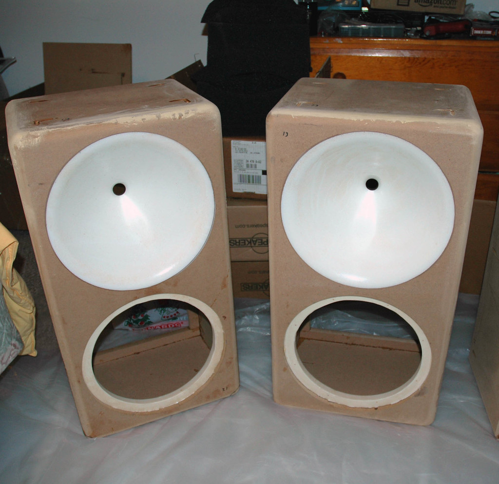
In the following sims, I will compare two extreme cases. The first case is a 25x25 degree horn, like the Danley SH-25. The second case is a 90x90 degree horn. Both horns use the same compression driver (A B&C DE25), both horns use the same midrange drivers (a quad of Misco JC5RTF-B), both horns have a mouth that is identical in size. Narrow angle horns are deeper than wide angle horns, and due to this the narrow horn is 43 liters versus 12 liters for the wide angle horn.
The 25x25 would look something like this, albeit half the length:
the 90x90 would look something like this, albeit 25% wider, and using a square mouth

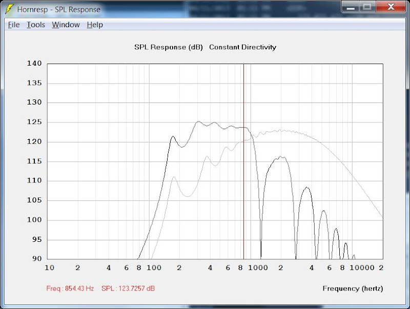
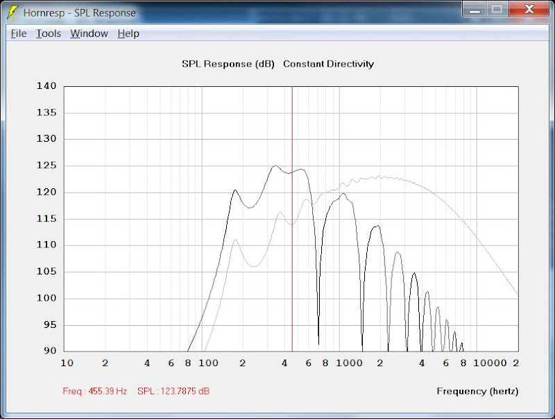
In the threee pics above, I've shown the effect of moving the midrange taps on the 25x25 degree horn. In the first pic, the taps are 5cm from the throat. In the second, it's 10cm, and in the third it's 20cm. Nothing else changed; mouth is same, volume is same, compression driver is same, etc...
Some observations:
1) Anything beyond 10cm is fairly ugly
2) In the sims I've placed a red vertical line that indicates where the throat reflection is expected. For instance, it's expected at 850hz with a 10cm 'tap.' In the hornresp sims, we see that the notch occurs higher in frequency than predicted and the location of the notch depends on wall angle.
3) A midrange horn needs a lower flare rate than a treble horn, and I think this is the reason that the 10cm 'tap' has the smoothest response in it's passband. While the 5cm location plays lower, because the mid 'sees' a longer horn than the 10cm location, the 10cm tap is less resonant in the passband. I think this might translate into superior sonics, since response 'blips' in the midrange are so noticeable due to the Fletcher Munson curves.
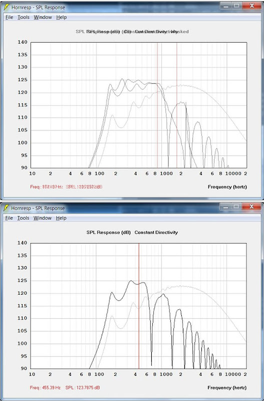
Here's all three graphs on one page.
One thing that's interesting is that the wattage on the compression driver is a LOT higher than on the mids. 100 watts for the mids, or 25 watts per mid, versus 500 watts for the compression driver. Probably one of the reasons that I've had good luck with very small mids; it doesn't take a lot of power to get the mids loud on the horn, but the compression driver takes some serious power to get going.
In my next post, I'll run the same sims for a 90x90 instead of a 25x25 horn.
Also, I believe that narrow angle Unity horns are easier to implement than wide angle Unity horns, and that's it's borderline impossible to get a wide angle Unity horn to work UNLESS you use very small midranges, a very large tweeter, or both. (The Danley SM-96, with a coverage angle of 60x90, uses a coaxial driver at the apex, which gets the mids very close to the compression driver.)
So let's explore these hypotheses.
In the following sims, I will compare two extreme cases. The first case is a 25x25 degree horn, like the Danley SH-25. The second case is a 90x90 degree horn. Both horns use the same compression driver (A B&C DE25), both horns use the same midrange drivers (a quad of Misco JC5RTF-B), both horns have a mouth that is identical in size. Narrow angle horns are deeper than wide angle horns, and due to this the narrow horn is 43 liters versus 12 liters for the wide angle horn.
The 25x25 would look something like this, albeit half the length:
An externally hosted image should be here but it was not working when we last tested it.
the 90x90 would look something like this, albeit 25% wider, and using a square mouth
In the threee pics above, I've shown the effect of moving the midrange taps on the 25x25 degree horn. In the first pic, the taps are 5cm from the throat. In the second, it's 10cm, and in the third it's 20cm. Nothing else changed; mouth is same, volume is same, compression driver is same, etc...
Some observations:
1) Anything beyond 10cm is fairly ugly
2) In the sims I've placed a red vertical line that indicates where the throat reflection is expected. For instance, it's expected at 850hz with a 10cm 'tap.' In the hornresp sims, we see that the notch occurs higher in frequency than predicted and the location of the notch depends on wall angle.
3) A midrange horn needs a lower flare rate than a treble horn, and I think this is the reason that the 10cm 'tap' has the smoothest response in it's passband. While the 5cm location plays lower, because the mid 'sees' a longer horn than the 10cm location, the 10cm tap is less resonant in the passband. I think this might translate into superior sonics, since response 'blips' in the midrange are so noticeable due to the Fletcher Munson curves.
Here's all three graphs on one page.
One thing that's interesting is that the wattage on the compression driver is a LOT higher than on the mids. 100 watts for the mids, or 25 watts per mid, versus 500 watts for the compression driver. Probably one of the reasons that I've had good luck with very small mids; it doesn't take a lot of power to get the mids loud on the horn, but the compression driver takes some serious power to get going.
In my next post, I'll run the same sims for a 90x90 instead of a 25x25 horn.

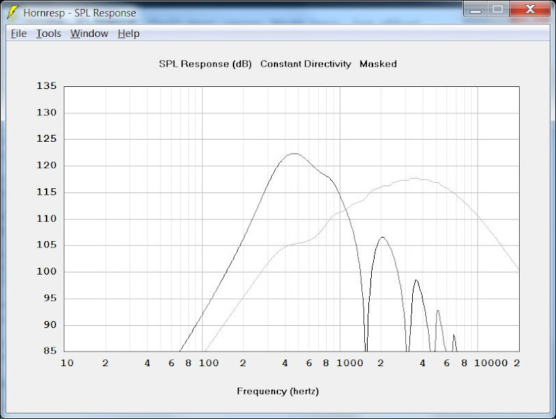
Continuing from the last post, here's a sim of a 90x90 degree horn, with a mouth that has an area of 1651cm (40.6cm x 40.6cm). (Same size mouth as the 25x25).
First pic uses midrange taps that are 5cm from the throat; second uses 10cm. The last compares both taps on the same graph, along with the compression driver. (B&C DE25)
Some observations:
1) If you're like me, the first thing you're going to notice with this 90x90 horn is that the compression driver is REALLY low. I actually double and triple checked my sims; they are correct. So it looks like the wider angle of the 90 degree horn is just CRUSHING the output of the compression driver, particularly at the low end of the compression driver. (right where we need it.)
It's really hard to make any comments about the midrange tap location when there's such obvious problems with the compression driver's output. The location of the midrange taps will basically be irrelevant until we address that, IMHO

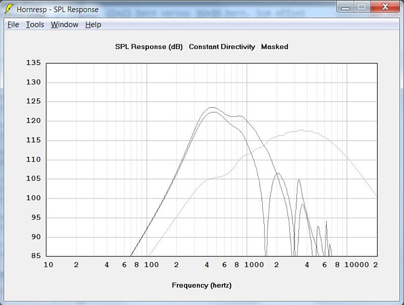
Here's the response of the same horn, but with the wattage adjusted to reduce the output of the mids, and increase the output of the compression driver.
Now it looks really nice 🙂
Unfortunately, the poor compression driver is just getting COOKED. It's getting one thousand watts in this sim, while the midrange array is getting 50, or just 12.5 watts per driver. In other words, the compression driver is getting EIGHTY times as much power as each mid is.
WHOAH :O
I guess I see why Danley needed the Layered Combiner for the Jericho horns.

Also helps explain why Bill and I have had good results with relatively wide angles, along with small midranges. Basically the wide angles put a big strain on the compression driver, so the wider the horn is, the harder it is on your compression driver. And due to that, you can get away with small mids when the angle is wide, because your compression driver will be working harder than nearly any midrange, even a 2" midrange. Another way to look at this is that those cheap Pyle mids, the ones that cost twelve bucks work well because they are just *loafing*. The wider those walls get, the harder that compression driver has to work, and those cheap Pyle mids are just taking a walk in the park at nearly any volume level that you'd listen to at home.
^^^ again, all of that is just my opinion, based on the sims and my understanding of how all these pieces fit together.
Last edited:
Unfortunately, the poor compression driver is just getting COOKED. It's getting one thousand watts in this sim, while the midrange array is getting 50, or just 12.5 watts per driver. In other words, the compression driver is getting EIGHTY times as much power as each mid is.
WHOAH :O
I guess I see why Danley needed the Layered Combiner for the Jericho horns.
..........at 120dB! Hardly a concern for home use I'd think. Though along the lines of your thinking, isn't it common practice to shelve down the low end of the comp driver to compensate for the CD horn gain? Which lowers the eff even more. I know you said you checked, but can that possibly be right? 1000 watts for 120dB on a horn?!
Patrick,1) If you're like me, the first thing you're going to notice with this 90x90 horn is that the compression driver is REALLY low.
Unfortunately, the poor compression driver is just getting COOKED. It's getting one thousand watts in this sim, while the midrange array is getting 50, or just 12.5 watts per driver. In other words, the compression driver is getting EIGHTY times as much power as each mid is.
^^^ again, all of that is just my opinion, based on the sims and my understanding of how all these pieces fit together.
Your opinion is based on compression driver power requirement sims that are off by at least an order of magnitude.
One only has to look at the impedance and sensitivity for DSL's Synergy horns to see how far off your compression driver models are.
I now understand why you have been thinking multiple HF drivers are needed, you have been basing your opinions on flawed models.
Art
Last edited:
..........at 120dB! Hardly a concern for home use I'd think. Though along the lines of your thinking, isn't it common practice to shelve down the low end of the comp driver to compensate for the CD horn gain? Which lowers the eff even more. I know you said you checked, but can that possibly be right? 1000 watts for 120dB on a horn?!
First off, I hope the information that I posted about the relationship between the coverage angle of the horn and the crossover point of the compression driver is useful. I've always struggled to get that transition right in my Unity horns.
I believe these sims are helping to illustrate my hypothesis, which is that a narrow angle horn allows for a lower xover point, which in turn makes it possible to use some drivers which are very attractive, such as 6.5" or even 8" mids.
I'm not going through all this for academic reasons; I have four compression drivers scheduled to arrive on Monday and I'm trying to decide if I want to use one per side or two.
Your first question is in regards to 'shelving' of the compression driver. Yes, we *do* use a shelving filter. And yes, the additional gain of a narrow angle horn will make a big difference.

My sims, using the B&C DE25 indicated that it would take a thousand watts to get the DE25 to 115dB at 1khz on a ninety degree horn. Reduce the coverage angle down to 25x25, and the power required drops tenfold; from a thousand watts to one hundred watts. The sim above shows the DE25 with one hundred and one thousand watts.
Your second question was, does it really take a thousand watts to get a DE25 to 120dB?
At 1khz, it takes about FOUR THOUSAND WATTS if you use a 90 degree horn. Narrow that down to 25 degrees and it'll require about four hundred.
Now the obvious question, is "who cares? No ones listening at 120dB at home."
In regards to that, I'm exploring this because I'm trying to figure out how to get the xover point down. I'm not trying to generate 120dB at 1khz; I'm trying to see if we can do 104dB at 500hz.

To get that crossover point down to 500hz, we need three things:
Displacement, power handling, and efficiency.
My hypothesis is that narrowing the angles of the walls will get us enough efficiency that the first two requirements aren't 'deal breakers' anymore. The graph above shows the displacement of the B&C DE25 on the 90x90 horn with a thousand watts, and the 25x25 horn with a hundred watts. In the sim, we see that the DE25 is hitting a wall at about 1khz on a 90x90 horn. This is consistent with my 'real world' experience. My Gedlee Summas use a DE250, a 90x90 waveguide, and an xover point of 900hz. But narrow that horn down to 25x25 and 'the wall' drops to about 500hz. That opens up a whole slew of driver options; the possibility of doing a two way synergy horn with hundreds of drivers that are 6.5" or even 8" in diameter.
The downside to all of this is that a 25x25 horn will 'illuminate' the listening room in a way that's quite unusual. Based on what I've read I think there's a strong case to be made for speakers with a coverage of 90x90 or even wider. But the cool thing about the Unity horns is that they can be arrayed, and that's the direction I'm leaning towards. Instead of a 90x90 horn picture two 90x45 horns that yield a combined pattern of 90x90.
Sims are well and good, but let's look at some 'real world' data:
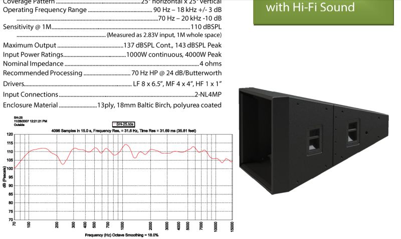
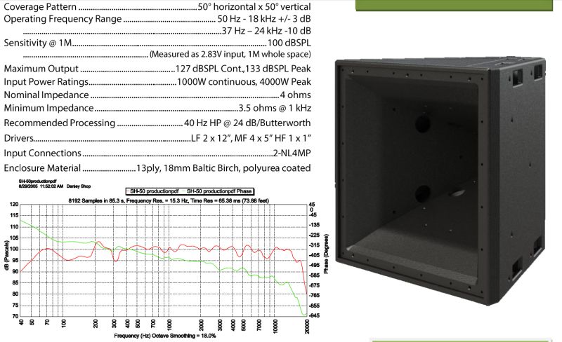
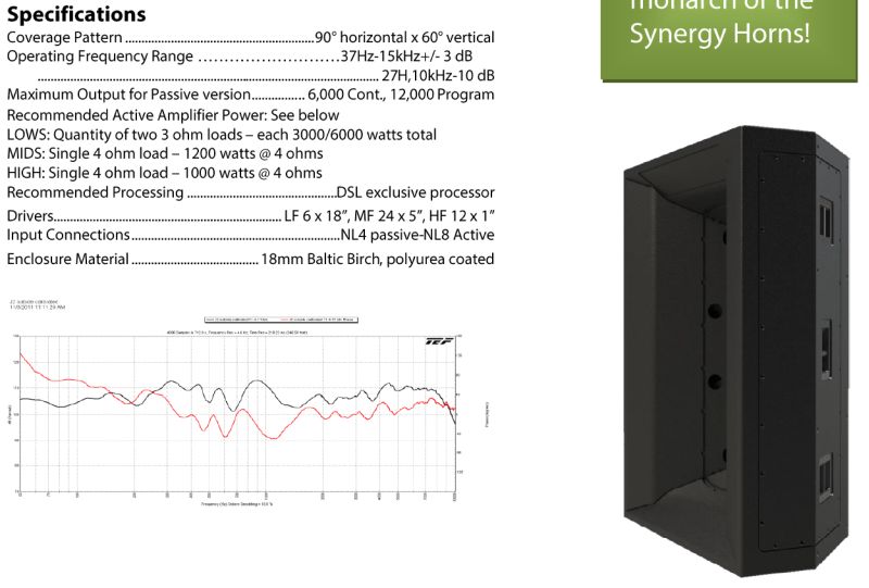
Here's the spec sheets for three synergy horns. The SH-25 has a coverage of 25 degrees, the SH-50 has a coverage of 50 degrees, and the Jericho 2 has coverage of 75 degrees. My hypothesis is that narrowing the coverage angle enable a lower xover point by increasing the efficiency. So let's see what the spec sheets tell us.
1) The SH-25, with a single BMS 4550, has an efficiency of 112dB at 1khz.
2) The SH-50, with a single BMS 4550, has an efficiency of 101dB at 1khz.
3) The Jericho 2, with twelve 1" compression drivers on a layered combiner and a coverage angle of 90x60, has an efficiency of 111dB at 1khz.
Note that the high frequency power handling of the SH-25 and the Jericho 2 are the same (1000 watts.) So unless I'm missing something, the narrow angle horn with one compression driver exceeds the maximum output of the wide angle horn with twelve compression drivers at one khz.
Obviously, a lot of this comes back to Hoffman's Iron Law. The SH-25 is a big box with a 23'^3 footprint. The SH-50 is half the size, at eleven and a half cubic feet. To get the 50x50 coverage of the SH-50 using four SH-25s would require 92 cubic feet, which exceeds the 43.75 cubic feet required by a Jericho 2.
It always comes back to Hoffman's Iron Law doesn't it 😛
So you're saying that on a 90x90 horn the DE25 needs 1kW to reach 115dBSPL @ 1m?
Which means its sensitivity at 1W in is just 115-30= 85 dBSPL/m @ 1W? Doesn't seem right.
Which means its sensitivity at 1W in is just 115-30= 85 dBSPL/m @ 1W? Doesn't seem right.
The ultimate sensitivity of any Synergy style horn is determined by the HF sensitivity, the wider the angle the less sensitive, a simple matter of directed energy.My sims, using the B&C DE25 indicated that it would take a thousand watts to get the DE25 to 115dB at 1khz on a ninety degree horn. Reduce the coverage angle down to 25x25, and the power required drops tenfold; from a thousand watts to one hundred watts. The sim above shows the DE25 with one hundred and one thousand watts.
At 1khz, it takes about FOUR THOUSAND WATTS if you use a 90 degree horn. Narrow that down to 25 degrees and it'll require about four hundred.
In regards to that, I'm exploring this because I'm trying to figure out how to get the xover point down. I'm not trying to generate 120dB at 1khz; I'm trying to see if we can do 104dB at 500hz.
In the sim, we see that the DE25 is hitting a wall at about 1khz on a 90x90 horn. This is consistent with my 'real world' experience. My Gedlee Summas use a DE250, a 90x90 waveguide, and an xover point of 900hz.
1) The SH-25, with a single BMS 4550, has an efficiency of 112dB at 1khz.
2) The SH-50, with a single BMS 4550, has an efficiency of 101dB at 1khz.
3) The Jericho 2, with twelve 1" compression drivers on a layered combiner and a coverage angle of 90x60, has an efficiency of 111dB at 1khz.
Note that the high frequency power handling of the SH-25 and the Jericho 2 are the same (1000 watts.) So unless I'm missing something, the narrow angle horn with one compression driver exceeds the maximum output of the wide angle horn with twelve compression drivers at one khz.
Obviously, a lot of this comes back to Hoffman's Iron Law. The SH-25 is a big box with a 23'^3 footprint. The SH-50 is half the size, at eleven and a half cubic feet. To get the 50x50 coverage of the SH-50 using four SH-25s would require 92 cubic feet, which exceeds the 43.75 cubic feet required by a Jericho 2.
Multiple drivers, summed properly, also increase efficiency and sensitivity.
You miss the point that your Gedlee Summas with a DE250, on a small a 90x90 waveguide work fine with a xover point of 900 Hz, increase the size of the horn, the same driver can be used much lower than that.
Your sims are obviously wrong, assuming a 98 dB sensitivity, the Summa would only take around 45 watts (not 1000) to hit 115 dB at 900 Hz.
Go back to your garage and measure the Summa horn, you'll see something is drastically off with your model. Also note that the lower portion of the HF output is attenuated some 10 dB or more compared to the HF, check the raw response of the driver and it will only take about 4.5 watts to do 115 dB.
You missed the point that an 8" driver on an offset horn can be crossed at 1000 Hz, as I am doing with my PA.
You missed the point that in the SH-25, SH-50 and the Jericho 2 the HF drivers are all crossed much higher than 1000 Hz.
You missed the point that the SH-25 power ratings are for the cabinet, put 1000 watts at of HF signal for more than an instantaneous peak and the HF driver will cook.
Your Hoffman's Iron Law observation is correct, it takes a much larger narrow horn to go as low as a wide angle horn 😉.
Art
Last edited:
So you're saying that on a 90x90 horn the DE25 needs 1kW to reach 115dBSPL @ 1m?
Which means its sensitivity at 1W in is just 115-30= 85 dBSPL/m @ 1W? Doesn't seem right.
I found where the error is. It's because I'm using hornresp to simulate the compression driver, and the value of VAS is at the limit of what hornresp allows. (0.01 liters)
Running sims on high frequency drivers is a p.i.t.a., and these parameters are the closest I could get to a working model*. IIRC, LeCleach has posted a model of a TAD driver, and Geddes has posted a model of the B&C.
Anyways, long story short, it appears that my model of the DE25 is off by an order of magnitude. To get proper numbers, one would have to add 10dB to all the curves, or multiply the wattage by 10. (I prefer the former, as the latter would screw up the excursion curves.)
If someone knows a way to get around this without using Akabak, please let me know.
To test my hypothesis about the efficiency of the compression driver, here's some sims.
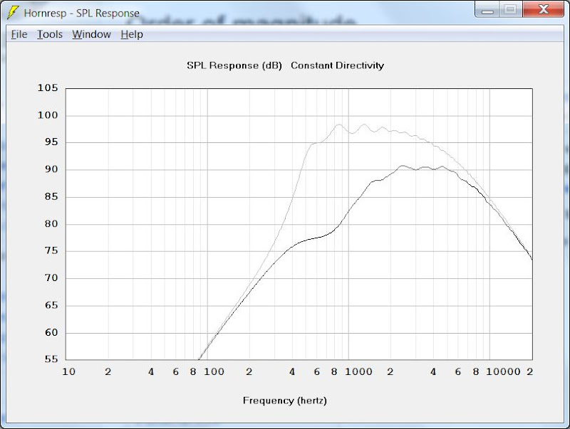
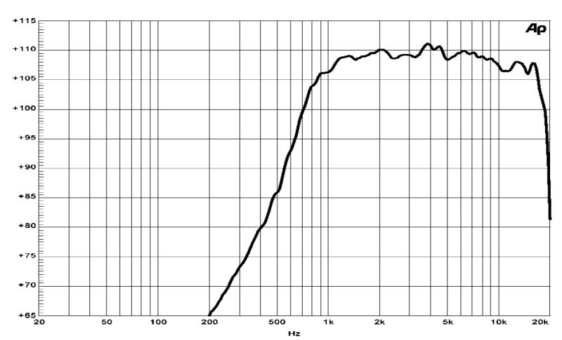
1) The first picture shows the predicted response of a B&C DE25 using my model on a 90x90 conical horn and the same driver on an exponential horn with a mouth of 433 square centimeters and a depth of 25cm. That's basically the same dimensions as the B&C ME45 horn used in B&C published spec sheet for the DE25 compression driver.
2) Second picture shows the published response of the DE25 on the ME45 exponential horn. We see that it's response is 12dB louder in it's passband. It's also smoother than hornresp predicts. (Hornresp typically exaggerates peaks and dips in the response.)
Despite all this, I'm still sticking to my hypothesis, that:
1) Given two horn with a mouth size that's equivalent but a wall angle that varies, the horn with the narrower angle will have higher on-axis output in the passband. (Hoffman's Iron Law)
2) Due to the increase in output, the horn with the narrower angle can be crossed over lower, if the output requirements are the same. Or it can play louder if the xover point is fixed.
3) Due to the challenge in getting the mids to play high in a Unity horn, a narrow angle Unity horn offers some advantages over a wide angle Unity horn.
* DE25 model is from here:Audio Psychosis • View topic - Simulating a B&C DE25
- Home
- Loudspeakers
- Multi-Way
- Suitable midrange cone, for bandpass mid in Unity horn