This version of the RIAA stage indicates how the 1st stage PNP transistor is biased. The BC557C/BC559C/BC560C gave the best performance of any cascoding device. High gm, high HFE and Hfe, Low capacitances are important.
The resistor R2 functions as a current source; and is used to avoid added noise of a semiconductor current source (for MC application). for larger signals, a true current source is better for distortion profile.

I have some FFTs somewhere, but taken many years ago, can't lay hands on them immediately.
The resistor R2 functions as a current source; and is used to avoid added noise of a semiconductor current source (for MC application). for larger signals, a true current source is better for distortion profile.
I have some FFTs somewhere, but taken many years ago, can't lay hands on them immediately.

Thanks Rod!! Great to see you thought, built and also optimized this circuit!
I will follow your suggestions!
I will follow your suggestions!
Hi Rod,
what about a 7812 in TO92 for the base of the BC559C, with the 24V to be supplied through a 7824 in TO220?
In the final amp I was thinking to derive the voltage at the input of the 7824 from the +48V of the class D amp through an RC of 1kOhm and 1000 uF 63V || 1 uF 100V poly to get a cleaner supply around 36V.
If the supply voltage is quiet enough, the resistor divider is OK for shunt cascode stage driving a power-amplifier with low input-current.
Is the input to this stage connected to a DAC?
DACs have a nominal voltage of 2V rms; many DACs have higher voltage - since the effective signal-to-noise ratio can be improved for higher voltage outputs.
If you can decide on your design-target for the input voltage, you can see if the noise of the chip-regulators (typically 0.003% of 24V, rms) is compatible with the design aims. In LTSPICE, Add the noise voltage to the supply, and look at the output, for a range of frequencies.
BTW, the input voltage limits the suitability of JFET stages: the bias voltage of the FET must accommodate the zero-to-peak input voltage. U440 and many other JFETs may not have enough bias range.
It's why I suggested lm317 instead of lm7824.@Elvee's denoisator might suit you well.7824 is also slower than 7805.You can use 7805 with a 20v zenner in series with 100ohm resistor on the adj pin or 3x 6v8 zenners shunted by 100nf caps and an ic driving it as in Technics sl-p990 regs. Preserving 7805 faster action with the aid of a zenner is underlined in Audionote DAC 4.I combined the two ideeas from Technics and Audionote into a very good regulator a few years ago.
Attachments
Last edited:
Thanks, the capacitor is connected to the positive side because it injects the filtered ripple to the base of the PNP and reduced the noise?If the supply voltage is quiet enough, the resistor divider is OK for shunt cascode stage driving a power-amplifier with low input-current.
Yes it is, it will be connected through a volume pot. There'sì indeed no need to have further gain to drive the class D amp: this line stage is just to emulate the harmonics of a tube amp.Is the input to this stage connected to a DAC?
DACs have a nominal voltage of 2V rms; many DACs have higher voltage - since the effective signal-to-noise ratio can be improved for higher voltage outputs.
100pF has no grip on 50/60hz hum in that circuit.Thanks, the capacitor is connected to the positive side because it injects the filtered ripple to the base of the PNP and reduced the noise?
C104 in this circuit does it:
Attachments
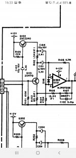
THe capacitor is 100µF - with a real Greek µ ! (AltGr→m on Linux keyboard)100pF has no grip on 50/60hz hum in that circuit.
"fast" regulation is not needed. An Elvee "de-noised" 317 would be OK, but a simple string of low voltage (BZX55) zeners, RC filtered (220µF→100Ω) and buffered with an emitter follower will be near-silent, and easy to construct7805 faster action
Why is there no need for fast response?
Think about the signal current: the FET and the output resistor currents always add up to the value of current in the current-source (the current-program resistor in this case); the supply current does not carry any notable signal component. This also means: No degradation from any power supply capacitors!
In that case, try running an ECC88 (or PCC89, PCC189, or various Soviet 6N2x series) from the supply voltage you already have.Yes it is, it will be connected through a volume pot. There'sì indeed no need to have further gain to drive the class D amp: this line stage is just to emulate the harmonics of a tube amp.
For example:
ECC88 45-60V supply; RC filtered. Grid bias ca. +3 - 5V. (positive bias improves DC stability, and allows more input voltage.
Rk: 680 - 1kΩ. NO cathode bypass capacitor, since you don't need gain. Ia: 6-9mA. Anode load resistor to suit the ouput.
It's so much simpler, by re-using the supply voltage you already have, and gives exactly what you need - the genuine harmonic cadenza.
- Home
- Amplifiers
- Tubes / Valves
- Suggestions for a non-tube line stage by SE tube expert