I need a passive filter to knock out the 19 kHz pilot for FM alignments as suggested in several procedures. A quick look at LC filters gave me huge L requirements for a reasonably high Z filter. I just want something to put on the scope input with reasonable slope. Don't want to power it. Suggestions?
Perhaps just a 19kHz notch? Still likely to need high value L though, around half as high as 10kHz LPF.
I need a passive filter to knock out the 19 kHz pilot for FM alignments as suggested in several procedures. A quick look at LC filters gave me huge L requirements for a reasonably high Z filter. I just want something to put on the scope input with reasonable slope. Don't want to power it. Suggestions?
A twin tee notch filter would work, with no L at all. It would even have small cap values.
Just use 1% precision caps, all of equal value, with two of them in parallel for the leg to ground.
RC Twin T Notch Filter :: Radio-Electronics.com
Last edited:
I need a passive filter to knock out the 19 kHz pilot for FM alignments as suggested in several procedures. A quick look at LC filters gave me huge L requirements for a reasonably high Z filter. I just want something to put on the scope input with reasonable slope. Don't want to power it. Suggestions?
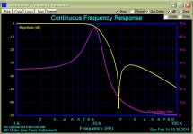
What are your exact requirements? Attached is a 4th order Butterworth with
10kHz BW and a 19 kHz Notch.
Input and output impedances are rather low to keep the L low.
Attachments

Last edited:
Now the OP just needs 10:1 matching transformers on the in and out to give him a 10k working impedance.
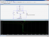
For such an application, I am fond of this type of rejector: it does not require matching, can give an infinite rejection with very imperfect components, the notch depth and frequency can be tweaked easily and separately, and it works with a very wide range of input and output impedances with little performance change.
In this example, the inductor is an ordinary 1mH choke and its loss parameters are compensated by R3+R5.
The exact frequency can be adjusted with a small parallel cap, C3.
Note that C1 and C2 do not even need to be exactly identical: you could use 100nF + 150nF for example.
If the inductor is very lossy, R3+R5 will have a low value, limiting the range of source impedances, but that's about the only limitation
Attachments
Now the OP just needs 10:1 matching transformers on the in and out to give him a 10k working impedance.
... or redesign the filter with higher impedances... i don't know what Conrad want to do with this filter and what the exact application is. So wait what he says.
But if he has opamps in mind an active filter would be easier to design.
And maybe he has an 10:1 transformer lying around...
Last edited:
From what he says it doesn't look like he has opamps in mind. He wants a filter that doesn't need power and he uses the phrase 'passive filter'. So I'd say opamps are ruled out.
10:1 transformers are fairly easy to make - I just made a 12:1 for my latest DAC design. I did need a winding machine though (because I'm too lazy to count turns) but such machines are quite affordable.
10:1 transformers are fairly easy to make - I just made a 12:1 for my latest DAC design. I did need a winding machine though (because I'm too lazy to count turns) but such machines are quite affordable.
The notch makes a lot of sense- thanks! The 19 kHz will be dead on, and I think that's the only thing I'm worried about filtering out. I did consider transformers, since an LC filter with low Z uses manageable inductors, but that was all just getting too complicated for the intended purpose. An opamp filter would be easy enough, but if I were going to bother with power I'd just plug in a commercial K-H filter and dial it up!
Not having tried it yet, I'm assuming the reason they specify a filter for FM alignments is so the 19 kHz residual doesn't contaminate the THD measurements while making those adjustments. I can't imagine that the 19 kHz residual would be large enough to bother anything else in terms of scope or meter readings.
Not having tried it yet, I'm assuming the reason they specify a filter for FM alignments is so the 19 kHz residual doesn't contaminate the THD measurements while making those adjustments. I can't imagine that the 19 kHz residual would be large enough to bother anything else in terms of scope or meter readings.
You could lift one from an old FM tuner. They all have some form since the 19 KHz pilot level is pretty high. I believe there are passive modules in some tuners.
You could lift one from an old FM tuner. They all have some form since the 19 KHz pilot level is pretty high. I believe there are passive modules in some tuners.
All so inclined should look before they leap. There is a good chance that the FM tuner at hand does not have 19 KHz filters, particularly if it was built in the last 20 years.
The 19 KHz pilot is about 20 dB down (10% deviation) and as it is essentially ultrasonic, it is often simply allowed to pass to the output terminals. It could cause problems with analog tape recorders using Dolby B processing.
In the day, passive analog filters were used to reduce the 19 KHz pilot tone - usually ellipitical filters made up of passive coils and capacitors.
However the filters to deal with it were probably more common in Dolby B adapters for tape recorders and analog tape recorders with Dolby B processing features.
I have checked the schematics of a number of modern FM stereo tuners and find that they generally omit 19 KHz filters.
In my service shop back in the seventies, I believe we just made up a simple series L/C network resonant at 19KHz and tied it across the scope input terminals. It was built into one of those little die-cast Pomona boxes with BNC I/O connectors, and I think it had a screwdriver trimmer capacitor to get the notch right where it belongs.
I checked and was reminded that the pilot signal is actually cancelled rather than notched in modern tuners. Its part of the typical MPX decoder circuit. 10% of full modulation is a lot and could fry tweeters in some cases. It is usually removed or nulled to some degree. It would be hard to get to .1% THD if it weren't. However that is not a circuit element that can be lifted. Older tuners may have a passive network. A simple LC tank may be the easiest to implement.
I think the dominant reason for notching out the pilot during alignment procedures was to reveal the optimum channel separation setting, i.e. the modulation null in the unmodulated channel. There's another strong reason for notch filtering built into demultiplexers: 19KHz leakage intermodulates with record bias in tape recorders, creating a noise problem that cannot be ignored.
- Status
- Not open for further replies.
- Home
- Design & Build
- Equipment & Tools
- Suggest a passive 10 kHz filter