Hello all! Newbie here.
I am planning on using the TPA3255 in PBTL mode to drive a subwoofer. I need help with a subwoofer filter design though on the analog input.
I am thinking of using the OPA1612AIDR , which seems really nice lol. For some reason though, I can't figure out how to make a simple active subwoofer (100hz) low pass filter. I am hoping for a -20dB/decade drop, but more would be great also.
I would really appreciate any tried and proven circuits, or ideas, tips, etc.
Thanks in advance!
Edit:
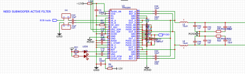
Attached is my current TPA3255 circuit. (I know it is pretty rough. I drew it quite a bit ago.)
I am planning on using the TPA3255 in PBTL mode to drive a subwoofer. I need help with a subwoofer filter design though on the analog input.
I am thinking of using the OPA1612AIDR , which seems really nice lol. For some reason though, I can't figure out how to make a simple active subwoofer (100hz) low pass filter. I am hoping for a -20dB/decade drop, but more would be great also.
I would really appreciate any tried and proven circuits, or ideas, tips, etc.
Thanks in advance!
Edit:
Attached is my current TPA3255 circuit. (I know it is pretty rough. I drew it quite a bit ago.)
Attachments
Last edited:
Hello @PRR !
I am not sure I understand your response 🤔 . I am trying to create a low pass active filter (using OPA1612AIDR op-amp) with a cutoff of 100hz and a slope of -20dB/decade (or more).
I am not sure I understand your response 🤔 . I am trying to create a low pass active filter (using OPA1612AIDR op-amp) with a cutoff of 100hz and a slope of -20dB/decade (or more).
Hi @wiseoldtech !
Hmmm, so I see that first, the audio in goes to a op-amp for amplifying, then to a op-amp acting like a buffer. The buffer is to prevent audio degrading over longer cables between the main board and the control board. Then, on the control board, the audio is fed to another op-amp that boosts the bass, then to another op-amp buffer for the trip back to the main board.
I have no distance problems, as the audio in and the amplifier are within inches of each other, so I just need to figure out the bass boost.
I have created a 100hz low pass filter using a chain of three RC filters then a BC548 transistor to amplify the resulting filtered audio. This "works" on a kind of subwoofer I have, but it definitely doesn't sound the best. I also know some about op-amps, but not much. I do know enough that I think I am looking for a 3rd order butterworth filter (right?).
A Sallen-Key toploogy is probably your go-to. Search: Analog application note op-amp filter design. Analog has a filter wizard, and Texas Instruments should have one, too.
Someone had a whole PDF book chapter on op-amp filters but I can't find it at the moment. Of you're not sure where to begin, a 4th order Linkwitz-Riley filter could be a good bet. The roll-off is slow for the filter order, but that makes it more stable and will prevent unwanted boom or overshoot.
Someone had a whole PDF book chapter on op-amp filters but I can't find it at the moment. Of you're not sure where to begin, a 4th order Linkwitz-Riley filter could be a good bet. The roll-off is slow for the filter order, but that makes it more stable and will prevent unwanted boom or overshoot.
Last edited:

Those boards are only a foot apart, so no issue with signal degrading.Hi @wiseoldtech !
Hmmm, so I see that first, the audio in goes to a op-amp for amplifying, then to a op-amp acting like a buffer. The buffer is to prevent audio degrading over longer cables between the main board and the control board. Then, on the control board, the audio is fed to another op-amp that boosts the bass, then to another op-amp buffer for the trip back to the main board.
I have no distance problems, as the audio in and the amplifier are within inches of each other, so I just need to figure out the bass boost.
I have created a 100hz low pass filter using a chain of three RC filters then a BC548 transistor to amplify the resulting filtered audio. This "works" on a kind of subwoofer I have, but it definitely doesn't sound the best. I also know some about op-amps, but not much. I do know enough that I think I am looking for a 3rd order butterworth filter (right?).
The whole thing can be built on one board.
Really? Hmmm.Those boards are only a foot apart, so no issue with signal degrading.
I'm a newbie clearly lol. From what I've read so far, I have seen that buffers are useful for stopping signal degradation. Why are they used in that schematic?
Thanks @abstract ! Searching now...
If you look at the schematic I posted, you'll see a Sallen-Key setup on the first IC.A Sallen-Key toploogy is probably your go-to. Search: Analog application note op-amp filter design. Analog has a filter wizard, and Texas Instruments should have one, too.
See, and you lost me alreadyIf you look at the schematic I posted, you'll see a Sallen-Key setup on the first IC.
 .
.That first op-amp circuit doesn't seem to be setup like this one (a Sallen-Key filter).
Attachments
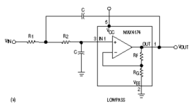
The first one on the left looks like a buffer ( probably very necessary), and the 2nd op-amp is configured as a high-pass, so the resistors and capacitors are swapped around. There is also a slight difference between unity gain S-K filters vs the ones with gain resistors.
Generally, it's not something that can be whipped up in an hour without a high chance of mistakes or reduced quality (e.g. a high noise design). I say take your time, use a spice simulator like LT spice or TINA, and good night from me for now.
Generally, it's not something that can be whipped up in an hour without a high chance of mistakes or reduced quality (e.g. a high noise design). I say take your time, use a spice simulator like LT spice or TINA, and good night from me for now.
EACH op amp is serving a different function, and several are configured for dropping the 'highs' in stages as seen in the print. C214-215-216-217....Really? Hmmm.
I'm a newbie clearly lol. From what I've read so far, I have seen that buffers are useful for stopping signal degradation. Why are they used in that schematic?
Thanks @abstract ! Searching now...
Again, consult the schematic to understand things.
Ah, that makes sense! Thanks @abstract , I was a bit confused why they were swapped. I haven't ever used LTSpice before either, so I am going to have to figure that out too.the 2nd op-amp is configured as a high-pass, so the resistors and capacitors are swapped around.
I am trying to understand your photo @wiseoldtech , but it is really blurry, and I'm getting a bit confused 😔.
On a side note, what is a buffer used for in audio?
Ah, that drawing is mis-labeled. The 2nd opamp is a unity-gain Sallen-Key high-pass. I do not know why it says "buffer". As you point out, there's about no reason to buffer between the first opamp and a short cable.Hmmm, so I see that first, the audio in goes to a op-amp for amplifying, then to a op-amp acting like a buffer.
Thank you @PRR for the clarification! That became a befuddled mess.
So if I get this straight, I should be aiming for a unity gain sallen-key low pass filter 🤔?
Ah, I found the service manual @wiseoldtech ! That is strange the schematic in the service manual to a Sony subwoofer would be mislabeled.
So if I get this straight, I should be aiming for a unity gain sallen-key low pass filter 🤔?
Ah, I found the service manual @wiseoldtech ! That is strange the schematic in the service manual to a Sony subwoofer would be mislabeled.
Not really strange at all.
Many service manuals have the occasional mistakes - you have to understand that they were written by humans who are not perfect.
Many service manuals have the occasional mistakes - you have to understand that they were written by humans who are not perfect.
Analog design handbook chapter 8
Check out the impulse responses of various filter types. Bessel is really good, as is linear phase to 12dB, but perfect matching with a high-pass to get summing to zero can be tricky. Butterworth might not work very well unless the drivers are closely spaced too cancel out any ringing.
Check out the impulse responses of various filter types. Bessel is really good, as is linear phase to 12dB, but perfect matching with a high-pass to get summing to zero can be tricky. Butterworth might not work very well unless the drivers are closely spaced too cancel out any ringing.
- Home
- Source & Line
- Analog Line Level
- Subwoofer Active Filter Help?