OK, let's not start a debate about whether an all-pass is a filter or not. I realise that I am jousting with a master here! Dodging sideways into another language is a move not open to me - I only have schoolboy French (I failed the exam!) and a very limited ability to pronounce Welsh place names (as my sister lives in Wales).
I am glad you guys are having fun! I am a little lost but find your banter interesting. Here is a simple question then. Do you have an opinion on the Citation 17 and what is the best way to approach restoring it. In your opinion is it sacrilege to increase capacitance in a predetermined circuit? Personally I find the the perception of the sound to improve when I have increased capacitance on the power and output board. I know to leave the phono preamp values in tact but what are acceptable tweaks used to squeeze performance out of a circuit design like mine? Are there any good rules of thumb you would recommend like put your best caps here in a circuit?
My rule of thumb is, if original designer did something it was done on purpose. However, in order to compete with other vendors the most expensive parts can't be always used in manufacturing, so sometimes it is possible to improve things swapping parts. But I am not familiar with Citation 17.
Indeed.conjecture and an incomplete understanding of what is occurring
Well, I was responding to a quip, the one about "truncation", delivered with what I took to be supreme confidence -which made it all the more laughable, I'm afraid. 🙂Is it your position that an analog signal is just as incomplete as a digital one. That a CD is of equal quality as an LP? or that by the time a digital or analog signal is processed they are all the same? I am opened to being educated so please enlighten me rather than just making quips.
That's what you think. For one, the vast majority of vinyl is cut from digital masters. So, if digital is fraught with one set of problems and analogue with another set of problems, then digitally mastered vinyl is sure to carry both sets of problems on its plucky little back. Furthermore CDs are not limited in any way in the bass. Vinyl is, for many reasons: one is that bass signals are attenuated by RIAA preemphasis curves (otherwise the grooves would be so wide, no cartridge would ever track them), the other is that nasty cartridge/tonearm resonance I mentioned, and there are others as well. It is also limited in the high treble, as those signals eventually become smaller than the curvature of the cartridge diamond tip and are therefore ignored by it. There is also another resonance lurking up there, the one caused by cartridge compliance and stylus mass, which makes HF response fall away like a ton of bricks. It all became very obvious in the heady old days of quadraphonic vinyl, which carried two extra channels encoded in ultrasound. It took some very extreme measures to build cartridges that would pick them up for decoding, and it was awash in noise and clicks anyway. Needless to say it flopped.Unlike CDs that are cut off from 20-20, Vinyl is not systematically limited.
Frankly, I'm not going to discuss pros and cons of vinyl vs Red book playback here. This discussion is being carried out all over the world for years and years by all audiophiles, several of which are far more knowledgeable than I am. The way I see it, digital is the only way to preserve audio signal intact forever. It may take 24/192 or 24/384 or 32/768 or infinite/infinite 😉 to surpass direct-cut vinyl, or analogue master tape at 15 ips, or whatever have you, but eventually it will. If industry could deliver an analogue recording and playback system that never deteriorated over time, with copying or without, I'd be all for it. But they won't because they can't, simple as that. So digital it is. Get over it. 🙂
Standing waves occur in a fairly limited wavelength range of about two or three octaves in the bass. The lowest frequency is the one, the half wavelength of which equals the room's longest dimension. The rest is, I'm afraidThe school of thought is that the extended and smooth frequency wave playback of vinyl contributes to the harmonic build up in the room and adds to the acoustic perception of space in the music. Even though most of us only hear between 20hz to 20khz the recorded playback above and below this frequency range contributes to the build up of standing waves in the room.
on your part.conjecture
I guess you hadn't listened to old 78 RPM playback
with replaceable needle every two-three records.
Low cut would then be determined by horn mouth diameter 😀
with replaceable needle every two-three records.
Low cut would then be determined by horn mouth diameter 😀
Yes, you have to start by assuming the designer knew what he was doing, unless you know enough to criticise his design. DIY 'upgrades' can improve one thing, while degrading two others. In some cases, however, the designer may have faced constraints which are no longer relevant.Wavebourn said:My rule of thumb is, if original designer did something it was done on purpose.
Yes, you have to start by assuming the designer knew what he was doing, unless you know enough to criticise his design. DIY 'upgrades' can improve one thing, while degrading two others. In some cases, however, the designer may have faced constraints which are no longer relevant.
Like, once one my amp designed in class A+C was "upgraded" by "Guru" to class AB... 😀
Yes, you have to start by assuming the designer knew what he was doing, unless you know enough to criticise his design. DIY 'upgrades' can improve one thing, while degrading two others. In some cases, however, the designer may have faced constraints which are no longer relevant.
I am starting to realize this more and more as I listen to the advice of most experts. One area that I am wondering about the most are the coupling caps in my amp. What about optimizing coupling caps for impedance matching as specified by the V-Cap website? This seems like an area that can be improved upon. Based on the V-Cap Website the coupling caps in my amp are at a value (.1uf) that seem to optimize bass response for a 4 ohm speaker at 38hz. An increase to .22uf would optimize bass response down to 20hz. I would venture to guess that the designer may have been forced to use a lower value to save money. Any thoughts on that? Since it is the last cap in the chain can it have consequences on the power supply or not likely?
You appear to be using "impedance matching" and "optimize" in a different way from their normal meaning. I haven't seen the V-Cap website, so maybe you are just repeating confusion you have seen there.AmCan said:What about optimizing coupling caps for impedance matching as specified by the V-Cap website? This seems like an area that can be improved upon. Based on the V-Cap Website the coupling caps in my amp are at a value (.1uf) that seem to optimize bass response for a 4 ohm speaker at 38hz. An increase to .22uf would optimize bass response down to 20hz.
Impedance matching is rarely an issue in audio; we normally want a significant mismatch. Changing a coupling cap to move the amplifier LF rolloff up or down is not "optimizing", unless you are trying to compensate for some peculiarity in the source or loudspeaker. An LF point of 38Hz is unlikely, so perhaps you have misunderstood something?
You appear to be using "impedance matching" and "optimize" in a different way from their normal meaning. I haven't seen the V-Cap website, so maybe you are just repeating confusion you have seen there.
Impedance matching is rarely an issue in audio; we normally want a significant mismatch. Changing a coupling cap to move the amplifier LF rolloff up or down is not "optimizing", unless you are trying to compensate for some peculiarity in the source or loudspeaker. An LF point of 38Hz is unlikely, so perhaps you have misunderstood something?
It is possible that I have misunderstood something. I need to take a basic electronics course. For your amusement here is the V-Cap Coupling Capacitor Calculator.
Coupling Capacitor Calculator by V-Cap
My speakers have an impedance of 4ohms and the current coupling capacitor has a value of .1uf If you look at the calculator and optimize for 8 Ohm speakers with .1uf coupling caps then it shows an optimal low frequency response of 20 Hertz. According to the calculator then changing the value of the coupling cap to .22 would optimize for 4ohm loads. Since this amplifier was originally manufactured back in 1978 when most speakers were not as power hungry as they are today or their Lf cutoff did not go as deep, I could imagine that the amp (Harman Kardon Citation 19) was not optimized to go that low for 4ohm speakers but of course I am not grasping the whole picture.
I think you're plugging in the wrong numbers. Unless there's an output coupling cap (rare), the speaker load is irrelevant- what counts is the resistance load following the coupling cap, which is likely to be 10k-1M ohm, depending on the circuit and where in the circuit the cap is used.
Personal note from someone who's been doing this stuff for longer than most people here have been alive: You are unlikely to find a real improvement in the sound (as opposed to the expected placebo after shelling out hundreds of dollars) of a decently engineered circuit by just popping in an ultraexpensive component. If you have a good quality polypropylene cap (a couple of dollars), further expenditure is for bragging rights, not actual performance. Willy-nilly replacement of components is a popular audiophile hobby since it doesn't require any actual electronics knowledge. The quality and honesty of your writing suggests that you could easily learn the electronics basics, and thus armed, could make the sorts of circuit changes that might actually increase performance rather than just costing money.
Personal note from someone who's been doing this stuff for longer than most people here have been alive: You are unlikely to find a real improvement in the sound (as opposed to the expected placebo after shelling out hundreds of dollars) of a decently engineered circuit by just popping in an ultraexpensive component. If you have a good quality polypropylene cap (a couple of dollars), further expenditure is for bragging rights, not actual performance. Willy-nilly replacement of components is a popular audiophile hobby since it doesn't require any actual electronics knowledge. The quality and honesty of your writing suggests that you could easily learn the electronics basics, and thus armed, could make the sorts of circuit changes that might actually increase performance rather than just costing money.
I think you're plugging in the wrong numbers. Unless there's an output coupling cap (rare), the speaker load is irrelevant- what counts is the resistance load following the coupling cap, which is likely to be 10k-1M ohm, depending on the circuit and where in the circuit the cap is used.
Personal note from someone who's been doing this stuff for longer than most people here have been alive: You are unlikely to find a real improvement in the sound (as opposed to the expected placebo after shelling out hundreds of dollars) of a decently engineered circuit by just popping in an ultraexpensive component. If you have a good quality polypropylene cap (a couple of dollars), further expenditure is for bragging rights, not actual performance. Willy-nilly replacement of components is a popular audiophile hobby since it doesn't require any actual electronics knowledge. The quality and honesty of your writing suggests that you could easily learn the electronics basics, and thus armed, could make the sorts of circuit changes that might actually increase performance rather than just costing money.
Thanks. Your point is well taken. When one first gets started in DIY, forums they are littered with suggestions of upgrades and my intuition is to ask not just how but also why. I will stick to basic value swap upgrades for now and revisit this when I can make my own determinations. Not to belabor the point but is this an output coupling cap in the schematic on the shaping board?
Attachments
If you're talking about C1, it's a Zobel cap, not coupling. Unless it's really, really bad, changing it will have close to zero effect on the performance. You don't want to change the value- what it does is helps keep the amp stable at very high frequencies under some odd (but possible) reactive loads. A cheap polypropylene is more than good enough.
a lossy MKT, or MKS would do in the Zobel location.
It should be completely inaudible if it is doing it's stability ensuring job correctly.
It should be completely inaudible if it is doing it's stability ensuring job correctly.
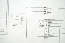
There is no getting around using this filter so I would at least like to try to change the cutoff frequencies to include as much of the audible frequency band as possible. First, I have no idea where the hi & low frequency cut off is occurring and 2nd what values I could substitute to extend the cut off. I would appreciate it if someone could help me modify this circuit. Having listened to this circuit the low cut off is not too bad considering my speakers are only flat down to 38 hertz. But the high frequency cut off is way too low. I would like to extend it to 20khz. Maybe 35hz to 20khz. I have attached the schematic. Any help or advice is appreciated.Great question , thou !
I also changed some caps in my preamplifier , leaving only the 1 µF electrolytic ,which is...in the subsonic filter !! Then lately I also re-discovered the beauty and perfection of vynil and turntable . And with some records at medium volume it really becomes unbearable to see those cones do the HOP ;
but putting the Subsonic filter it really does nasty things , no good ,you know ,it puts a veil...
So I think it's a real problem ,when listening at medium/ high volume ,but it has to be related with the whole : mechanical damping /isolation of the turntable =>electronic chain =>speakers and feedback make the circle again.
So the first things to do would be to eliminate or correct the possible causes ,in other words to put every piece of the chain outside audio band resonance.
Attachments
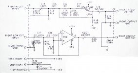
You have there two Sallen-Key filters, one high pass (low cut) and and low pass (high cut).
The high pass uses an opamp, wired as a follower. The frequency response is set by R21,R22, C17,C18.
The low pass uses a BJT emitter follower. Frequency response set by R15,R16, C14,C15.
Do a web search for Sallen-Key filter. The standard circuits will refer to R1, R2, C1, C2 so you need to match these to your circuit. There are always two components in series feeding the follower input (Rs or Cs). Then there is a component to ground at the follower input (C or R), and a component (C or R) from the follower output back to the junction of the two series components. The actual numbering may vary from one author to another so I won't confuse you by trying to second-guess here.
PS if you move the filter frequencies outside the audio band then all they will do is add phase shift, without actually reducing any unwanted signals - better then to simply omit them. With the Sallen-Key you need to calculate both frequency and Q.
Last edited:
You have there two Sallen-Key filters, one high pass (low cut) and and low pass (high cut).
The high pass uses an opamp, wired as a follower. The frequency response is set by R21,R22, C17,C18.
The low pass uses a BJT emitter follower. Frequency response set by R15,R16, C14,C15.
Do a web search for Sallen-Key filter. The standard circuits will refer to R1, R2, C1, C2 so you need to match these to your circuit. There are always two components in series feeding the follower input (Rs or Cs). Then there is a component to ground at the follower input (C or R), and a component (C or R) from the follower output back to the junction of the two series components. The actual numbering may vary from one author to another so I won't confuse you by trying to second-guess here.
PS if you move the filter frequencies outside the audio band then all they will do is add phase shift, without actually reducing any unwanted signals - better then to simply omit them. With the Sallen-Key you need to calculate both frequency and Q.
Thanks for pointing me in the right direction. There are several calculators available to help determine values. I need to spend some time absorbing this information. The concept seems simple but I am not an engineer and some of the language is beyond my knowledge base. Meaning I still don't know what to do but I would like to change the resistor values because I have already selected some nice capacitors for this circuit.
- Home
- Source & Line
- Analog Line Level
- Subsonic Filters & Film Caps