Hi ShinOBIWAN,
I agree with you and that's my conclusion also, but you explained it better 😉
I must say that my experience with the DEQX team always has been positive. Especially Alan Langford has been helpful and very service minded.
Do you use the "reference calibration kit" or the standard kit? I recently bought the "reference kit" with the DM30 microphone, but I'm still waiting for the DEQX calibration mic file. Hopefully there will be a couple of notch better accuracy with that microphone.
/Goran
Hey Goran
Yes I use the DM23 mic which is essentially a rebadged Earthworks M23 with DEQX calibration files also included. I would have liked to have gone for the M30 but the gf would have killed me and I value life more than another 7Khz of ultrasonic resolution 😀
I've had three DEQX now. The first was the PDC2.6 about 5 years ago and I used the standard calibration kit with this. I had this upgraded around 2007 to the HDP3 spec but sold the machine the following year after finding the PC route to give better quality. I lived with the PC for a couple of years but eventually, despite the quality, I grew tired of the effort required and went back to a DEQX. This time the Express since money is tighter these days and the exchange rate less favourable.
In terms of sound I'd rank the DEQX I've tried as HDP3>Express>PDC2.6. A PC equipped with Acourate or AudioLense is capable of beating them all with a good external sound interface such as the RME Fireface 800 etc but its own issues are apparent. I'd only ever go FIR filtering for music on the PC and stick with IIR for AV because otherwise delay issues are gonna drive you almost insane.
I've tried too many digital filtering methods over the years and overall considering the pro's and con's of each I think the DEQX is the most rounded of them all. Go PC if your after that extra 5% of performance and don't mind working under the hood but you do need a great sound interface to get the best from it and that usually means the PC works out as expensive as a DEQX Express (about £1300 imported to the UK).
I'm intrigued by your measuring of off-axis angles. How do you incorporate each of the angled correction filters into the final result? I was not aware that the DEQX could do this.
You can average multiple results but I wouldn't recommend creating a correction filter that incorporates off axis correction. It just doesn't work very well. Best is to correct on axis and if the design is good then off axis will take care of itself.
Hi ShinOBIWAN,
Thank you for the information. 🙂
I also started with a PDC 2.6, bought second hand with the digital out option installed and later on upgraded it to a HDP-3.
I must say that the sound from the PDC 2.6 wasn't that great, but the functionality intrigued me. With the upgrade to HDP-3 the sound quality entered the high-end world, even though sometime I think the sound is a bit to polite and neutral for my taste. 😀
I'm a bit curious how it would sound with different DACs connected to the digital out board. I might test it in the future.
The reason for choosing the Earthworks m30 was that I wanted to use it for other measurement purposes also, besides the DEQX. I wanted a microphone that could accurately measure tweeter dome break-ups, which normally occurs between 20-30kHz. Another reason was that I got a 25% discount from DEQX on the m30. 😀
I'm intrigued by your measuring of off-axis angles. How do you incorporate each of the angled correction filters into the final result? I was not aware that the DEQX could do this.
Hi JoshK,
No you are correct. The DEQX cannot handle that, but I configure each correction filter (0, 15, 22.5 and 30 degrees) to one of the four presets. In this way I can just press a button on the remote to change the correction filter from listening position and evaluate which one who sounds best.
I also use the above presets when doing my verification measurements. More on that in a later post.....
The reason for choosing the Earthworks m30 was that I wanted to use it for other measurement purposes also, besides the DEQX. I wanted a microphone that could accurately measure tweeter dome break-ups, which normally occurs between 20-30kHz. Another reason was that I got a 25% discount from DEQX on the m30. 😀
🙂
Yep they do give decent discounts if you've been spending money with them for awhile. I got about the same off my mic and I think I even managed to get around 10% off the Express with a bit of haggling even though they don't normally discount this model. Still too bloody expensive for what it is but what can you do in a market where's there's little to no better choices. I hope minidsp and hypex can put together something that's competitive with the DEQX platform in the future.
BTW, I had the digital preouts fitted on my PDC2.6/HDP3 and used it with a Lynx Aurora 16 DA. Definitely an improvement over the standard converters but less so with HDP3 which already has quite decent ones.
You can average multiple results but I wouldn't recommend creating a correction filter that incorporates off axis correction. It just doesn't work very well. Best is to correct on axis and if the design is good then off axis will take care of itself.
I don't fully agree with you 😉, but as you say it depends a lot on how the design e.g. enclosure shape and driver behavior etc looks like.
I this study I will show some of the off-axis effects by using correction filters.
/Goran
Measurement verification:
I have done four different correction filters based on 0, 15, 22.5 and 30 degrees off-axis measurements.
Each correction filter is measured at an angle of 0, 15, 22.5, 30, 45 and 60 degrees. Both woofer and tweeter are measured individually as well as the summed driver response plus a measurement with the tweeter connected in reverse polarity. This gives a total of 96 measurements for each loudspeaker…….
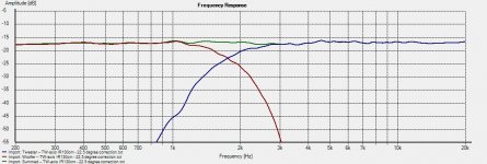
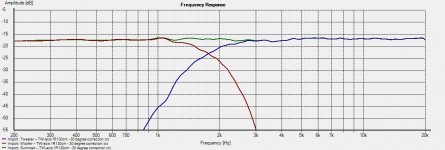
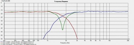
First of all I’ll show how a 0 degrees correction filter looks like on-axis, 0 degrees (Picture 1). The small ripples higher up in frequency are due to artefacts from microphone grip reflections (Loudspeaker Measurements). (Picture 2) shows the same measurement, but with a 1/12 octave smoothing. All subsequent measurements will be shown with a 1/12 octave smoothing. (Picture 3) shows the tweeter connected with reverse polarity.
Note 1, almost ruler flat 😀, but there is one strange thing……. Remember, all the correction filters I’ve done used a 2000Hz cross-over frequency! The actual cross-over frequency is 1750Hz and this is the case through out all verification measurements….hmmm. I wonder why?
Picture 4: 15 degrees correction filter, 15 degrees off-axis.
Picture 5: 15 degrees correction filter, 15 degrees off-axis and tweeter reverse polarity.
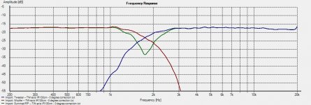
Picture 6: 22.5 degrees correction filter, 22.5 degrees off-axis.
Picture 7: 22.5 degrees correction filter, 22.5 degrees off-axis and tweeter reverse polarity.
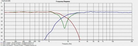
Picture 8: 30 degrees correction filter, 30 degrees off-axis.
Picture 9: 30 degrees correction filter, 30 degrees off-axis and tweeter reverse polarity.
Note 2, Ok, what does all this mean? Yes, you get ruler flat responses for the measurement angles you have made a correction filter for. If you toe-in your speakers to aim directly at you, you get a ruler flat from the 0 degrees correction filter. If you don’t toe-in your speakers, you get ruler flat responses from the 15-30 degrees correction filter, depending on the angle to the listening position.
Is this the whole truth? No, unfortunately not…... We also need to handle baffle diffraction and how a specific correction filter behaves off-axis and the power response.
Next, measurements and off-axis responses……
I have done four different correction filters based on 0, 15, 22.5 and 30 degrees off-axis measurements.
Each correction filter is measured at an angle of 0, 15, 22.5, 30, 45 and 60 degrees. Both woofer and tweeter are measured individually as well as the summed driver response plus a measurement with the tweeter connected in reverse polarity. This gives a total of 96 measurements for each loudspeaker…….
First of all I’ll show how a 0 degrees correction filter looks like on-axis, 0 degrees (Picture 1). The small ripples higher up in frequency are due to artefacts from microphone grip reflections (Loudspeaker Measurements). (Picture 2) shows the same measurement, but with a 1/12 octave smoothing. All subsequent measurements will be shown with a 1/12 octave smoothing. (Picture 3) shows the tweeter connected with reverse polarity.
Note 1, almost ruler flat 😀, but there is one strange thing……. Remember, all the correction filters I’ve done used a 2000Hz cross-over frequency! The actual cross-over frequency is 1750Hz and this is the case through out all verification measurements….hmmm. I wonder why?
Picture 4: 15 degrees correction filter, 15 degrees off-axis.
Picture 5: 15 degrees correction filter, 15 degrees off-axis and tweeter reverse polarity.
Picture 6: 22.5 degrees correction filter, 22.5 degrees off-axis.
Picture 7: 22.5 degrees correction filter, 22.5 degrees off-axis and tweeter reverse polarity.
Picture 8: 30 degrees correction filter, 30 degrees off-axis.
Picture 9: 30 degrees correction filter, 30 degrees off-axis and tweeter reverse polarity.
Note 2, Ok, what does all this mean? Yes, you get ruler flat responses for the measurement angles you have made a correction filter for. If you toe-in your speakers to aim directly at you, you get a ruler flat from the 0 degrees correction filter. If you don’t toe-in your speakers, you get ruler flat responses from the 15-30 degrees correction filter, depending on the angle to the listening position.
Is this the whole truth? No, unfortunately not…... We also need to handle baffle diffraction and how a specific correction filter behaves off-axis and the power response.
Next, measurements and off-axis responses……
Attachments
-
 Picture 1.jpg250.4 KB · Views: 532
 -
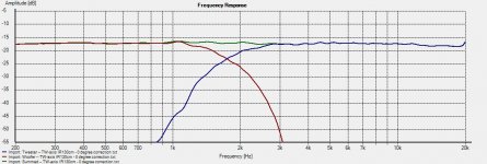 Picture 2.jpg243.5 KB · Views: 522
 -
 Picture 3.jpg245.8 KB · Views: 513
 -
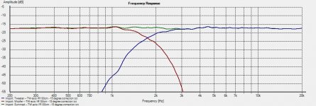 Picture 4.jpg244.9 KB · Views: 512
 -
 Picture 5.jpg247.9 KB · Views: 506
 -
 Picture 6.jpg246.4 KB · Views: 149
 -
 Picture 9.jpg248.5 KB · Views: 165
 -
 Picture 8.jpg245.7 KB · Views: 170
 -
 Picture 7.jpg250.1 KB · Views: 147
I hope I’m not misrepresenting him, but I believe that soongsc made a recommendation regarding mic position when calibrating UE (ultimate equalizer).
IIRC it related to placing the mic closer than half the diameter of the (smallest?) driver.
I presume that this would reduce the noise floor substantially i.e. not calibrating the environment.
It would also avoid calibrating the (acoustic) diffraction manifestations.
I have long tried using this sort of technique, with success, when calibrating my DEQX.
A close distance is chosen for the tweeter, and the mic is moved vertically for all the other measurements, with scrupulous attention paid to keeping each position the same distance to the listening position.
In fact, by doing it this way it is the same distance to virtually every off-axis position as well
(for DEQX users this requires “prompt between drivers”).
Worth a comparison.
David
Hi David,
Thank you for your input. It´s feedback like this I was hoping for when I started this thread. 🙂
Since DEQX moved to the new Forum the Forum activity almost died out. It´s very interesting to hear how other DEQX owners have find ways to use it differently and making it sound as good as possible.
Since I truncate the measurement windows, I don't measure the environment (room influence), but I do get the effects of baffle step and baffle diffraction in my measurement.
By moving the mic closer, let´s say to 0.25-0.5meter the baffle diffraction won't be eliminated, but perhaps reduced. By doing a real near-field measurement as suggested (1-2cm) will cause other issues as now the baffle diffraction and baffle step is removed, but added after the correction filter is applied with unpredictable results.
It could also be quite hard, but not impossible to move the mic up and down while keeping the exact same distance to the baffle. Another issue would be that DEQX would think that both drivers radiates from the same point (co-axial) in this kind of measurement, despite the fact that they are separated by 12-13 cm on the baffle. Chances are that this would give some phase issues and unpredictable results at the listening position.
I find your measurement technique interesting and will try it and verification measure it as soon as I have my new measurement mic in place.
Do you use the standard or the reference calibration kit? If so do you experience any sound improvement when using the reference kit for calibration?
/Goran
Could you comment on the steep linear phase slopes used. Any draw backs? I have wanted the DEQX for 4 years now. I have the DCX, MiniDSP, Hypex DSP solutions and Im just waiting for the best DEQX deal. I can do a 60dB slope with cascading functions on the MiniDSP but I do not think I can do a linear phase Slope 🙁
I look forward to your measurements.
as far as I am aware you can use custom biquad functions in minidsp if so you can do a FIR filter. Use matlab according to wikipedia octave should also have the relevent algorithms built in. Parks-McClellan method works quite well for designing FIR filters from my experaince.
Hi Goran
I only use the Earthworks reference mic.
The baffle step is difficult.
My speakers are dipoles, so it is not an issue.
Floor bounce might be.
It will require different correction for different listening positions (distances), and height of speaker(s).
I think it is best to get at it at source.
I get away with it (I hope!) by using a vertical array of drivers up to 400Hz.
Seems to work (not your 2-way solution though- although it can be if you use mid/tweeter such as the Jordan Jxr6hd or Alpair, or alternatively, maybe, a higher crossover to a waveguide e.g. an econowave).
I'd have to have a bit more of a think about the baffle step issue.
Wayne Parhams's solution would also work, as I believe would Mandrakes's.
I'm not sure that the coincidence issue matters, as when measuring from one position, it still works no matter how far apart the drivers are (they are still after all actually independent measurements). BTW Alan Langford approves.
With baffle diffraction, I don't think DEQX can remedy that.
It has to be corrected at source.
I believe you're right that the speaker MUST be designed so that the off-axis response is consistent (not necessarily identical) with the on axis response i.e. some sort of CD.
David
Member
Joined 2009
FIR in DSP
I'm interested in learning more about this approach. Can you point me to a sample implementation. I'm mostly interested in a flat phase Linkwitz-Riley crossover. What would be the best way to arrive there?
as far as I am aware you can use custom biquad functions in minidsp if so you can do a FIR filter. Use matlab according to wikipedia octave should also have the relevent algorithms built in. Parks-McClellan method works quite well for designing FIR filters from my experaince.
I'm interested in learning more about this approach. Can you point me to a sample implementation. I'm mostly interested in a flat phase Linkwitz-Riley crossover. What would be the best way to arrive there?
Measurements and off-axis responses:
As I mention earlier in this thread, I made four different (0, 15, 22.5 and 30 degrees) correction filters. Each of them have a ruler flat response when measured at the same angle as the correction filter, but what happens with the frequency response when measured off-axis?
The baffle step and the baffle diffraction have to be taken into account in the design of the loudspeaker.
The baffle step is quite easy to handle in the DEQX. You simply adjust the amount of the baffle step compensation by adjust the lower limit of the correction filter. In this case, 250Hz for a full baffle step compensation and e.g. 500Hz for a half baffle compensation or somewhere in between according to personal taste.
The baffle diffraction is the major issue in this design. The baffle diffraction effect can be reduced by arrange the drivers optimally on the baffle, by enclosure shape and design, but never completely eliminated. Different drivers are also more or less sensitive to diffraction.
The following described measurements make this baffle diffraction and its effects more clear.
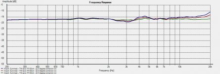
0 degrees correction filter:
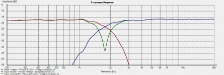
Picture1: Blue = 0 degrees, Red = 15 degrees, Green = 22.5 degrees
Picture2: Blue = 30 degrees, Red = 45 degrees, Green = 60 degrees
Note: Looks nice in the 0 degrees angle, but the correction filter overcompensates (2500-3500Hz) in the off-axis frequency response.
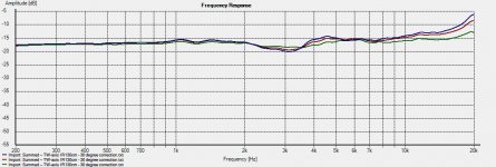
15 degrees correction filter:
Picture3: Blue = 0 degrees, Red = 15 degrees, Green = 22.5 degrees
Picture4: Blue = 30 degrees, Red = 45 degrees, Green = 60 degrees
Note: Looks a bit better and the correction filter doesn’t overcompensate as much in the off-axis frequency response.
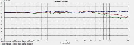
22.5 degrees correction filter:
Picture5: Blue = 0 degrees, Red = 15 degrees, Green = 22.5 degrees
Picture6: Blue = 30 degrees, Red = 45 degrees, Green = 60 degrees
Note: Here the correction filter overcompensates a bit higher up in the frequency response (4000-5000Hz).
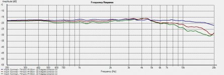
30 degrees correction filter:
Picture7: Blue = 0 degrees, Red = 15 degrees, Green = 22.5 degrees
Picture8: Blue = 30 degrees, Red = 45 degrees, Green = 60 degrees
Note: Here the correction filter makes a dip in the frequency response (2500-3500Hz) and with a slight rising response higher up in the frequency.
I listened to each of the four correction filters for a couple of day before I made these measurements to see which correction filter I found sounds the best. In the listening test the speakers had the same setup with no toe-in and a listening angle of approximately 15-22.5 degrees.
Subjectively I found the 15 or the 22.5 degrees correction filter to sound the best and the 0 degrees correction filter to sound the worst. By looking at the off-axis responses I can see why. None of the correction filters did sound bad, but they all had a different sonic character.
The DEQX unit have other features, e.g. a digital EQ that I haven’t used in this test and which can be used to tailor the frequency response and sound further.
Now when I have a deeper knowledge of how these specific driver units in this specific enclosure behave, I can redo the measurement with my recently bought “reference” microphone and tailor the sound with the EQ function and then redo my test measurements to verify the design.
I will be back with a final design, stay tuned….
As I mention earlier in this thread, I made four different (0, 15, 22.5 and 30 degrees) correction filters. Each of them have a ruler flat response when measured at the same angle as the correction filter, but what happens with the frequency response when measured off-axis?
The baffle step and the baffle diffraction have to be taken into account in the design of the loudspeaker.
The baffle step is quite easy to handle in the DEQX. You simply adjust the amount of the baffle step compensation by adjust the lower limit of the correction filter. In this case, 250Hz for a full baffle step compensation and e.g. 500Hz for a half baffle compensation or somewhere in between according to personal taste.
The baffle diffraction is the major issue in this design. The baffle diffraction effect can be reduced by arrange the drivers optimally on the baffle, by enclosure shape and design, but never completely eliminated. Different drivers are also more or less sensitive to diffraction.
The following described measurements make this baffle diffraction and its effects more clear.
0 degrees correction filter:
Picture1: Blue = 0 degrees, Red = 15 degrees, Green = 22.5 degrees
Picture2: Blue = 30 degrees, Red = 45 degrees, Green = 60 degrees
Note: Looks nice in the 0 degrees angle, but the correction filter overcompensates (2500-3500Hz) in the off-axis frequency response.
15 degrees correction filter:
Picture3: Blue = 0 degrees, Red = 15 degrees, Green = 22.5 degrees
Picture4: Blue = 30 degrees, Red = 45 degrees, Green = 60 degrees
Note: Looks a bit better and the correction filter doesn’t overcompensate as much in the off-axis frequency response.
22.5 degrees correction filter:
Picture5: Blue = 0 degrees, Red = 15 degrees, Green = 22.5 degrees
Picture6: Blue = 30 degrees, Red = 45 degrees, Green = 60 degrees
Note: Here the correction filter overcompensates a bit higher up in the frequency response (4000-5000Hz).
30 degrees correction filter:
Picture7: Blue = 0 degrees, Red = 15 degrees, Green = 22.5 degrees
Picture8: Blue = 30 degrees, Red = 45 degrees, Green = 60 degrees
Note: Here the correction filter makes a dip in the frequency response (2500-3500Hz) and with a slight rising response higher up in the frequency.
I listened to each of the four correction filters for a couple of day before I made these measurements to see which correction filter I found sounds the best. In the listening test the speakers had the same setup with no toe-in and a listening angle of approximately 15-22.5 degrees.
Subjectively I found the 15 or the 22.5 degrees correction filter to sound the best and the 0 degrees correction filter to sound the worst. By looking at the off-axis responses I can see why. None of the correction filters did sound bad, but they all had a different sonic character.
The DEQX unit have other features, e.g. a digital EQ that I haven’t used in this test and which can be used to tailor the frequency response and sound further.
Now when I have a deeper knowledge of how these specific driver units in this specific enclosure behave, I can redo the measurement with my recently bought “reference” microphone and tailor the sound with the EQ function and then redo my test measurements to verify the design.
I will be back with a final design, stay tuned….
Attachments
-
 0 degree correction -- 0-22.5 degree off-axis.jpg238.6 KB · Views: 565
 -
 0 degree correction -- 30-60 degree off-axis.jpg248.4 KB · Views: 571
 -
 15 degree correction -- 0-22.5 degree off-axis.jpg239.2 KB · Views: 548
 -
 15 degree correction -- 30-60 degree off-axis.jpg247.6 KB · Views: 551
 -
 22.5 degree correction -- 0-22.5 degree off-axis.jpg241 KB · Views: 543
 -
 22.5 degree correction -- 30-60 degree off-axis.jpg247.9 KB · Views: 161
 -
 30 degree correction -- 0-22.5 degree off-axis.jpg242.8 KB · Views: 147
 -
 30 degree correction -- 30-60 degree off-axis.jpg248.9 KB · Views: 178
as far as I am aware you can use custom biquad functions in minidsp if so you can do a FIR filter. Use matlab according to wikipedia octave should also have the relevent algorithms built in. Parks-McClellan method works quite well for designing FIR filters from my experaince.
Well, are you sure ?
custom biquads will only let you design custom IIR filter that's all.
FIR will need a completely different technique
Best from France
Jean-Claude
Advanced Biquad programming | miniDSP
Pretty sure as a FIR filter is charcterised by polls only a z=0 which is clearly posible from the stated biquad transfer function. If your a* coefficiants are zero you should have an FIR filter.
*for the linear phase characteristic that is desirable the b coefficiants should be symetrical before the filter is decomposed into biquads.
Last edited:
I'm interested in learning more about this approach. Can you point me to a sample implementation. I'm mostly interested in a flat phase Linkwitz-Riley crossover. What would be the best way to arrive there?
A linkwitz-Riley crossover is as far as I'm aware not a linear phase filter therefore there is no advantage apart from stability to using a FIR filter. The Linkwitz-Riley is just a filter that ensures that drivers are in phase at the crossover point and add with 0dB gain.
As for designing FIR filters look at the matlab help for the following commands:
firpm
firpmord
However looking at my lab notes I don't think the mini dsp is powerfull enough to implment good enough FIR filters as I used a 51st order filter to make one pretty poor bandpass filter and the mini dsp only has 68 biquads which would be pretty quickly used up.
Sorry to ruin your thread here...
I've just gotten my HDP Express II 'up and running', wanting to take it slow and measure some speakers etc. First issue I encounter is that I am not able to find any calibration file for the DM23 microphone... The CD supplied contains files for CM30/CMX30 and DM30 mic's.
I've tried downloading any new files (incl firmware) from DEQX' site, but seems I need a UN/PW?
No users manual was included, so I must admit I'm stumbling in the dark here...
Sorry to ruin your thread here...
I've just gotten my HDP Express II 'up and running', wanting to take it slow and measure some speakers etc. First issue I encounter is that I am not able to find any calibration file for the DM23 microphone... The CD supplied contains files for CM30/CMX30 and DM30 mic's.
I've tried downloading any new files (incl firmware) from DEQX' site, but seems I need a UN/PW?
No users manual was included, so I must admit I'm stumbling in the dark here...
Register a support request!
DEQX High Definition Audio
The mic files that can be downloaded from the site is very old and you need the mic file for your mic. Send DEQX your mic serial number in order to get the correct mic file.
Regards
/Göran
P.S. check your PM
Did that early this morning and have received the file needed.
(Thanks for the tip though).
Now I just gotta wait for the spring, - measuring the speakers indoors was not a success.
Main area of interest is below 80Hz and I'm not able to get anywhere close to decent measurements for the low frequencies.
(Thanks for the tip though).
Now I just gotta wait for the spring, - measuring the speakers indoors was not a success.
Main area of interest is below 80Hz and I'm not able to get anywhere close to decent measurements for the low frequencies.
- Status
- Not open for further replies.
- Home
- Loudspeakers
- Multi-Way
- SU551-RS28F – a 2-way DEQX system loudspeaker measurement study