This might look weird to you guys, but I wanted to confirm it before doing some home-made explosions:
The 0V is supposed to be connected to PIN 3?
IN- is supposed to be connected to PIN 2?
Are all grounds supposed to be on the same network?


The 0V is supposed to be connected to PIN 3?
IN- is supposed to be connected to PIN 2?
Are all grounds supposed to be on the same network?
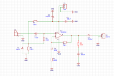
This is called a single supply circuit.
The inputs are biased up to half the DC supply voltage by R1, R2, R3. The input is at the usual (+) pin #1,
passed through a coupling capacitor to block the DC voltage that is at pin #1 from the input source.
All grounds are the same.
More info: https://www.ti.com/lit/an/sloa030a/sloa030a.pdf
The inputs are biased up to half the DC supply voltage by R1, R2, R3. The input is at the usual (+) pin #1,
passed through a coupling capacitor to block the DC voltage that is at pin #1 from the input source.
All grounds are the same.
More info: https://www.ti.com/lit/an/sloa030a/sloa030a.pdf
Last edited:

So, no need for SE- and 0V to be imputed then, for what I understood.
What about the Resistors Power Rating? 250 or 500mW would be enough?
And R6 as well? Or it should be 1W or more?
Thanks
What about the Resistors Power Rating? 250 or 500mW would be enough?
And R6 as well? Or it should be 1W or more?
Thanks
All resistors are low power except R6, which could dissipate quite a bit of power in some circumstances.
Perhaps 5W is acceptable as a compromse.
Perhaps 5W is acceptable as a compromse.
I built a circuit very much like this some years ago. Because of the high current load of the speaker, the voltage Vs (with respect to ground) dropped a bit when the speaker demanded current (at the positive peaks of the signal).
The voltage across R2 and C2 is a fraction of the power supply voltage, and is connected to the amplifier + input. The loop thus formed can cause a low-frequency oscillation. When I had that problem, I made C2 bigger which simply lowered the frequency of oscillation. What worked for me was to replace R2 with a zener diode rated for half the voltage Vs. This will bias the amplifier output at Vs/2 (with respect to ground), about where you want it. If battery powered, Vs will drop a bit between recharges or replacements. This will make the constant bias a bit less than optimal for a low battery but a small price to pay for stability.
It could be that my power supply was not "firm" enough; that is, it didn't take much current to change the voltage. You may not have this problem.
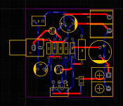
Also put C3 close to the chip. Identify high-current paths and use low-resistance (i.e., large diameter) wires for them.
Tom
The voltage across R2 and C2 is a fraction of the power supply voltage, and is connected to the amplifier + input. The loop thus formed can cause a low-frequency oscillation. When I had that problem, I made C2 bigger which simply lowered the frequency of oscillation. What worked for me was to replace R2 with a zener diode rated for half the voltage Vs. This will bias the amplifier output at Vs/2 (with respect to ground), about where you want it. If battery powered, Vs will drop a bit between recharges or replacements. This will make the constant bias a bit less than optimal for a low battery but a small price to pay for stability.
It could be that my power supply was not "firm" enough; that is, it didn't take much current to change the voltage. You may not have this problem.
Also put C3 close to the chip. Identify high-current paths and use low-resistance (i.e., large diameter) wires for them.
Tom
Any reason to why the datasheet puts an electrolyte capacitor for blocking DC, and not Ceramic or PP?
But do they have the same performance? Or the difference in cost over ceramic or PP is not worth it?
There is seldom a realistic option if larger uF values are needed, except in speaker crossovers.
Even then, the film capacitor cost will be much higher than for an electrolytic type.
Even then, the film capacitor cost will be much higher than for an electrolytic type.
You don't need Big 5W resistor for R6, 1-2w usually enough. I used 1W metal oxide there. Interestingly my friends destroyed this chip couple of time but i never saw a burned R6. OTOH the value of the output capacitor isn't optimal, you need at least 2200uf or maybe more to get decent low frequencies.

C4 should be 0.47uF not 4.7uF
If C1 & C2 are ecap, use correct symbol on schematic as they are polarised. Positive electrode, for both, is connected to the TDA. You don’t need big and expensive film cap for such amp, ecap are ok.
If C1 & C2 are ecap, use correct symbol on schematic as they are polarised. Positive electrode, for both, is connected to the TDA. You don’t need big and expensive film cap for such amp, ecap are ok.
Questions are never stupid - that's the role of answers.
Yes!
//
Yes!
//
C1 is film, not that big and not very expensive
C2 is polymer, not electrolyte, not expensive as well
C2 is polymer, not electrolyte, not expensive as well
C3 is too small, you need at least 22uf there & C4 should be 0.47uf not 4.7uf !!
All caps should be electrolyte?C4 should be 0.47uF not 4.7uF
If C1 & C2 are ecap, use correct symbol on schematic as they are polarised. Positive electrode, for both, is connected to the TDA. You don’t need big and expensive film cap for such amp, ecap are ok.
I am taking a guess here, but I bet that I am correct. If you have a 4.7uf electrolytic capacitor in circuit, then often times it is bypassed by say a .1uf or similar FILM capacitor. The film cap will be physically small in size and easily fit on the board.
So some capacitors are electrolytic and others are film.
So some capacitors are electrolytic and others are film.
I was referring to C1 & C3, not C2. Sorry for the mistake.All caps should be electrolyte?
C1 & C3 could be film or electrolytic, but you won’t notice nor mesure difference for this kind of amp. 4,7uF electrolytics will be smaller and cheaper than film.
C2 is typically an electrolytic, no need to have a polymer.
C4 , 0.47uF, is typically a film.
C6 is a film or a ceramic. If ceramic choose its voltage rating 2 to 3 time the supply voltage as most of ceramics have their value related to the voltage at their terminals.
- Home
- Amplifiers
- Chip Amps
- Stupidest questions ever?