

You don't have to modify anything. The T27 is connected to a high pass filter, not a band pass. So it gets the full spectrum from a few kHz up.
Are you connecting the original B139 B110 T27 combo?
What puzzles me is that this filter is from a high-end English design from the late 1970-ies. Atkinson State-of-the-Art, Roger's Monitor. But the components (electrolytics, iron core inductors) don't look good at all. For sure the electrolytics have dried out and lost much of their value. Most of them can be replaced with MKM. And only L1 might be ferrite, not even iron.

Thanks for replying,
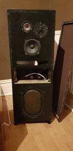
Well I have 2 Transmission Line speakers, one I believe is original Pro9TL Mk1 and the other I don't know much about. The TL in question has a Mid by celestion "DYNAMIC" range and Tweeter I think it's from Bang n Olifson? I will show you pictures. The both are extremely well made for their time, I wish to "clean up" the sound somewhat, bring them out from the dark and into the light if you get what I mean.
Well I have 2 Transmission Line speakers, one I believe is original Pro9TL Mk1 and the other I don't know much about. The TL in question has a Mid by celestion "DYNAMIC" range and Tweeter I think it's from Bang n Olifson? I will show you pictures. The both are extremely well made for their time, I wish to "clean up" the sound somewhat, bring them out from the dark and into the light if you get what I mean.
Yes Pro 9 TL also used this combo. Either augmented with the super tweeter or not. The high pass filter does not change. You can see that in the top schematic that you posted in your second post.
The design of the bandpass filter for the B110 IS critical though. Replacing the B110 by "something else" and keeping the same filter could lead to non-satisfactory results. At least I was unsuccessful in my attempt.
Recently I measured the Fs of my 40-year old B139. It had increased to 43 Hz! And I am not the only one where that happened. The B139 was an awesome driver but unfortunately now it is ready for the scrap bin. I hope your drivers had a better life and ageing. But it is worth checking them.
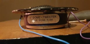
Thay both have ample amount bass, I will have to check. Pro9 is in amazing condition and original (baught by me from builder) however, this one in question i baught from second owner who I believe made these changes. B139, celestion mid, H086 Tweeter and Coles ST is driver line up.
Link to thread with more detailsYes Pro 9 TL also used this combo. Either augmented with the super tweeter or not. The high pass filter does not change. You can see that in the top schematic that you posted in your second post.
The design of the bandpass filter for the B110 IS critical though. Replacing the B110 by "something else" and keeping the same filter could lead to non-satisfactory results. At least I was unsuccessful in my attempt.
Recently I measured the Fs of my 40-year old B139. It had increased to 43 Hz! And I am not the only one where that happened. The B139 was an awesome driver but unfortunately now it is ready for the scrap bin. I hope your drivers had a better life and ageing. But it is worth checking them.
https://www.diyaudio.com/community/...e-need-help-to-figure-every-thing-out.412634/
Bazza - When removing the ST, I suggest you disable its HF filter by breaking the connection between C7 and the + input.
This will prevent any possibility of amplifier damage due to an unloaded filter.
This will prevent any possibility of amplifier damage due to an unloaded filter.
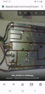
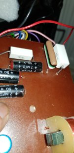
Something bothers me, Bazza - I don't see any correlation between your photo of the crossover and the schematic you have furnished.
Just compare the number of inductors for a kick-off.
Just compare the number of inductors for a kick-off.
is it any of these I need to remove
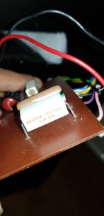
All I can say is that the smallest value capacitor in your photo is the tan film one with the coloured stripes.
You could remove it to see if your ST stops working.
As for trying to interpret a schematic from your photos, that would only put my old head in a spin!

You can only hope that someone with an eye for these things may accommodate you.
The one with the colored stripes is likely 1,000,000 pf = 1 uF. Makes sense. I don't think one of the schematics actually matches the PCB.
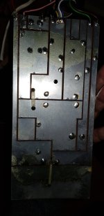
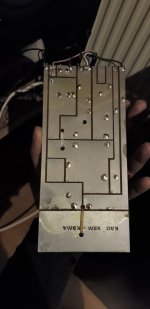
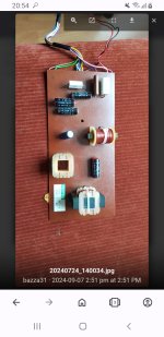
To draw a schematic, hold the PCB against a light source with the component side facing you. Put the components in your drawing and draw lines according to the PCB traces. It is not rocket science just work. Like we did in the old days when component were still recognizable.
The capacitors have their value written on them. As for the inductors, the one with the most windings have the largest inductance. Those with cores have larger inductance than without. But the actual value is not important anyway. Those have been selected by the designer of the filter. You just want to know what is connected to what.
Didn't we draw this once?Would these pics help to draw a proper diagram

- Home
- Loudspeakers
- Multi-Way
- Stupid question but just maybe?