Legis V-horn Synergy with 3.75 liter compression chambers
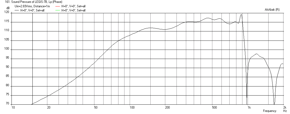
I found a typo in my script that was producing the ripples (the rear chamber on one of the drivers had a very long characteristic length of 128 inches instead of 12 in!). What is the depth of the 30 liter box anyway? It does affect the simulation, as well as how much stuffing you use in there. The response is smoother now but also seems to have a rise starting at 200 Hz. Here is the 3.75 liter driver chamber - almost same as my initial guess of 4 liters 🙂 with the injection port length of 2.75 cm and 11 cm dia, located at 11.7 cm.
I found a typo in my script that was producing the ripples (the rear chamber on one of the drivers had a very long characteristic length of 128 inches instead of 12 in!). What is the depth of the 30 liter box anyway? It does affect the simulation, as well as how much stuffing you use in there. The response is smoother now but also seems to have a rise starting at 200 Hz. Here is the 3.75 liter driver chamber - almost same as my initial guess of 4 liters 🙂 with the injection port length of 2.75 cm and 11 cm dia, located at 11.7 cm.
Attachments
I found a typo in my script that was producing the ripples (the rear chamber on one of the drivers had a very long characteristic length of 128 inches instead of 12 in!). What is the depth of the 30 liter box anyway? It does affect the simulation, as well as how much stuffing you use in there. The response is smoother now but also seems to have a rise starting at 200 Hz. Here is the 3.75 liter driver chamber - almost same as my initial guess of 4 liters 🙂 with the injection port length of 2.75 cm and 11 cm dia, located at 11.7 cm.
Now we are talking, looks really nice and easy to xo. How's the phase/group delay? The null is at 2x xo frequency as should be. The 9:1 compression ratio seems to boost sensitivity a little, especially from 200Hz upwards?
That 3,75 litre front chamber does not seem to cause much acoutical low pass. Does the Akabak take the "mass break point" of the driver into account, ie. if you increase the Mms or decrease the Bl, the upper frequencies get attenuated more?
The depth is 20cm. The back chamber is 39cm* 39cm* 20cm from the inside, so 30,5 litres net, minus the driver (-2,38l), plus the acoustical damping material's effective bonus, so we arrive pretty close, or slightly north of 30 litres.
Move Injection Port to 21 cm from throat
Legis,
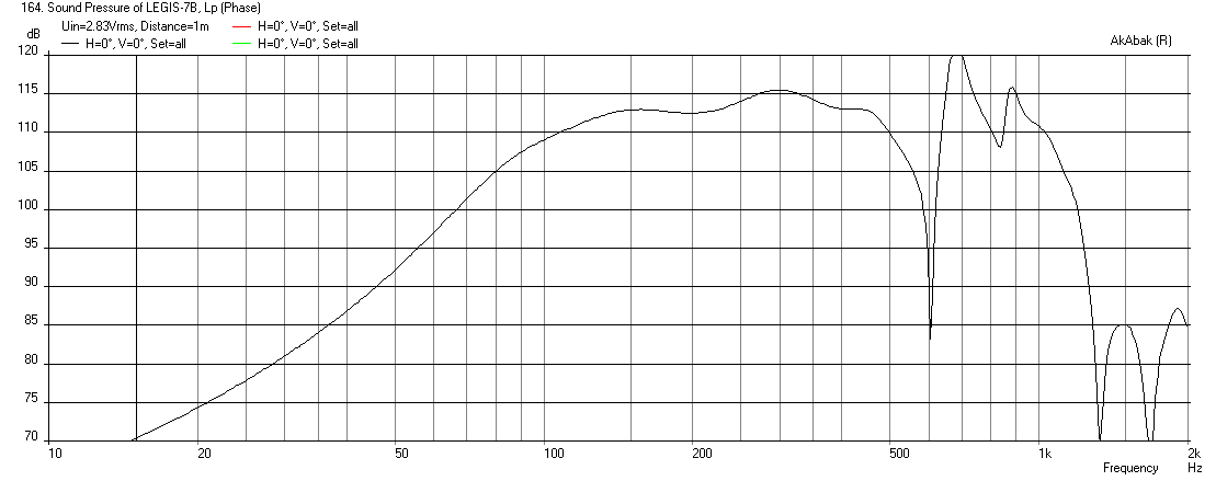
Here is a sim with the 11 cm dia injection port located at 21 cm from the throat (21 cm axially on centerline, so us projected position on horn wall). It seems to have just the right natural cutoff for a 500Hz crossover, provides a natural acoustic XO to supplement the electrical one. Also, I feel that the overall response looks more balanced and has less of a rising slope now. You can split the injection port into multiple holes/slots just keep the same CSA. This is with an 8in rear chamber depth (about 20cm), so good there. Akabak does indeed include the Mms of the driver - or mass corner. This is looking like it could be a pretty good horn.
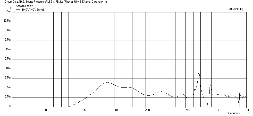
Here is the group delay for this configuration - looks excellent all under a few ms over 100 Hz to 500 Hz:
Legis,
Here is a sim with the 11 cm dia injection port located at 21 cm from the throat (21 cm axially on centerline, so us projected position on horn wall). It seems to have just the right natural cutoff for a 500Hz crossover, provides a natural acoustic XO to supplement the electrical one. Also, I feel that the overall response looks more balanced and has less of a rising slope now. You can split the injection port into multiple holes/slots just keep the same CSA. This is with an 8in rear chamber depth (about 20cm), so good there. Akabak does indeed include the Mms of the driver - or mass corner. This is looking like it could be a pretty good horn.
Here is the group delay for this configuration - looks excellent all under a few ms over 100 Hz to 500 Hz:
Attachments


Last edited:
Legis,
Here is a sim with the 11 cm dia injection port located at 21 cm from the throat (21 cm axially on centerline, so us projected position on horn wall). It seems to have just the right natural cutoff for a 500Hz crossover, provides a natural acoustic XO to supplement the electrical one. Also, I feel that the overall response looks more balanced and has less of a rising slope now. You can split the injection port into multiple holes/slots just keep the same CSA.
It seems that some movement of injection port would be possible. But there are also huge resonances just after the null. They can (of course) be nothed away in the crossover but a true X order decreasing slope is easier to obtain if there are no resonances near the xo point. Some similarity/application note suggestions can be applied from metal cone woofers - best to be crossed at an octave or more below the cone resonance. 🙂
You have a good point about avoiding resonances near XO freq. It may be a tradoff between how a 11 cm dia hole affects the HF horn performance when near the throat vs dealing with a resonance near the XO point. Since you have built it already I guess you will try the near location first.
It would be neat if you could make a circular plate that fits into the sidewall of the horn with the port, This plate could be rotated to change the location of the injection port and you can tune the system for optimum HF and XO behavior.
It would be neat if you could make a circular plate that fits into the sidewall of the horn with the port, This plate could be rotated to change the location of the injection port and you can tune the system for optimum HF and XO behavior.
You have a good point about avoiding resonances near XO freq. It may be a tradoff between how a 11 cm dia hole affects the HF horn performance when near the throat vs dealing with a resonance near the XO point. Since you have built it already I guess you will try the near location first.
It would be neat if you could make a circular plate that fits into the sidewall of the horn with the port, This plate could be rotated to change the location of the injection port and you can tune the system for optimum HF and XO behavior.
I may be able to measure the HF section of the horn tomorrow or the day after that.
By the way, can Akabak simulate the effects of those injection ports with a compression driver, can it code such anomalies to the horn?
Yes and no. The model is 1-dim lumped element, so anything that is a physical dimension or lensing 3d type effect (such as having edges, holes, etc near a throat of the CD) is not captured. However, the hole near the throat presents a path of low acoustic impedance into the driver chamber. This is captured in the model from the standpoint of a network of impedences. You can see this by applying drive signal to one driver and monitoring the EMF generated on the passive driver - the acoustical energy from one driver couples into another. I would guess that running a CD and monitoring the woofer voicecoil will yield a voltage - albeit, small. The farther away from the throat the holes are located, the closer it will become like a 1-d lumped element model. The closer the hole is the CD throat, the more 3d it is and less accurate to be modeled in Akabak. If you use a 3d finite element analysis (FEA) model like ABEC3, it should capture this effect much more accurately.
Also, good models of a CD for Akabak are few and far in between. The only one I have seen really modeled is the DE-250 and that has not been verified. If using the CD, both CD and woofers need to be part of same system. I split them into two systems (non-interacting) so that I could apply independent XO's.
The presence of a driver cone to contain the space in the driver chamber behind the injection hole is critical to the response. You might fake it with a big dinner plate etc. until your real Deltalites come.
Also, good models of a CD for Akabak are few and far in between. The only one I have seen really modeled is the DE-250 and that has not been verified. If using the CD, both CD and woofers need to be part of same system. I split them into two systems (non-interacting) so that I could apply independent XO's.
I may be able to measure the HF section of the horn tomorrow or the day after that.
The presence of a driver cone to contain the space in the driver chamber behind the injection hole is critical to the response. You might fake it with a big dinner plate etc. until your real Deltalites come.
Last edited:
Deltalites are here tomorrow. On the edge of first "beta" listening session after that... 🙂
An externally hosted image should be here but it was not working when we last tested it.
Wow!!! That system is humongous! 🙂
What does SWMBO have to say about all this? Love it! 🙂
Impressive indeed. Looking forward to first sound from a 110dB sensitive 3 way horn speaker system.
What are you using for active XO/EQ and amps?
What does SWMBO have to say about all this? Love it! 🙂
Impressive indeed. Looking forward to first sound from a 110dB sensitive 3 way horn speaker system.
What are you using for active XO/EQ and amps?
Last edited:
Thanks! She actually dislikes their appearance, can't understand that.😛 4 ways, horn super tweeters also. I have to put them inside the synergies also, either hang them in the air or make some stand for them. 🙂
Suspend the super tweeters with 4 wire spider at mouth of horn. That will look cool.
What are you using for XO and amps? I see the big rack mounts in the photo but can't make out the brands. Looks like you may have way too much power given that they are 110dB sensitive. 😀
What are you using for XO and amps? I see the big rack mounts in the photo but can't make out the brands. Looks like you may have way too much power given that they are 110dB sensitive. 😀
Aesthetics aside, a tweeter placed in the mouth will not time align with the rest of the horn output off axis. If time aligned on axis, it will progressively lag in time off axis, causing comb filtering and progressive "dullness", as what we hear first sounds loudest (Haas effect).Suspend the super tweeters with 4 wire spider at mouth of horn. That will look cool.
Unfortunately, the other alternative, placing the tweeter and the midrange at the same on axis acoustic center (roughly aligning the voice coils vertically) is messed up by reflection of the HF off the top of the mid horn.
What are you using for XO and amps? I see the big rack mounts in the photo but can't make out the brands. Looks like you may have way too much power given that they are 110dB sensitive. 😀
XO is MiniDSP Nanodigi 2x8, for amps I have right now 4 channels of ab-class pro amps, 2 channels of high bias monoblocks and 2 channels of chinese 10w tripath. The high sensitivity might push the system into SE tube amp direction... 🙂
Super tweeter is only for the last octave or so, not the most critical application. I have to see what to do with them.
Last edited:
It feels like the 15" driver choice was a success, they sound IMO very good without an xo (I always like to listen to drivers as-is first). The curvilinear profile unribbed cone and very open chassis seems to tame all the bell resonances of the driver. Natural sounding and easy to work with. The low weight is pretty amazing too.
An externally hosted image should be here but it was not working when we last tested it.
An externally hosted image should be here but it was not working when we last tested it.
Last edited:
Very nice. Once you put it on the horn for size comparison the injection port looks tiny at 11cm. I guess that is a pretty high compression ratio and part of the reason why the horn works so well. Mainly the small injection port controls the high frequency cutoff. Have you measured actual compression chamber volume yet? Looking forward to first sound. 🙂
Life got slightly in the way of hifi today, did not get proper test system up yet.
Right now I'm listening to the Deltalites in the horn without the back chambers (only one horn playing). The bass and snares have nice attack. JBL 2446J is also playing along without any xo (it's 10pm and I'm listening softly so they don't get too much bass).
On-axis response from the listening spot, no xo's, no time aligment etc..
Sounds very good given the circumstances. Balance is good even though the Hf response decreases like that. The sensitivity of these things match quite nicely.
I suspect that this specific 2446J has some dirt in the air gap because it sounds like it in sweeps between ~100-500Hz. Also visible in the third harmonic plot. I have to open it tomorrow and see what's going on.
I will damp the back chambers tomorrow and put them on.
I have not even bought/downloaded the NanoDigi's software yet😀. Have to do some these "little" things tonight.
Right now I'm listening to the Deltalites in the horn without the back chambers (only one horn playing). The bass and snares have nice attack. JBL 2446J is also playing along without any xo (it's 10pm and I'm listening softly so they don't get too much bass).
On-axis response from the listening spot, no xo's, no time aligment etc..
An externally hosted image should be here but it was not working when we last tested it.
Sounds very good given the circumstances. Balance is good even though the Hf response decreases like that. The sensitivity of these things match quite nicely.
I suspect that this specific 2446J has some dirt in the air gap because it sounds like it in sweeps between ~100-500Hz. Also visible in the third harmonic plot. I have to open it tomorrow and see what's going on.
I will damp the back chambers tomorrow and put them on.
I have not even bought/downloaded the NanoDigi's software yet😀. Have to do some these "little" things tonight.
What's it look like without the compression driver?
Blue is the original response with 2446J, red is solo Deltalites without the back chambers, yellow is undambed back chambers put on loosely on the backside of the drivers. Mic's position is not accurate between the measurements, these are just quick tests (from listening position at 2,5m away from the speaker in a concrete wall room).
I'll make more proper measurements in the next few days.

Last edited:
- Status
- Not open for further replies.
- Home
- Loudspeakers
- Subwoofers
- Study of a Dipole/Cardioid Bass Horn