I am hoping someone from this forum can give me some suggestions and design tips on how to get this circuit working. What I want to have happen is this -- plug a guitar directly into the circuit and have two LEDs mirror the dynamics of the sound while the guitar is being played. One LED will be lit as the guitar is idle, when the guitar is played this LED will dim to darkness and the other LED will come to life and light itself based on how hard the guitar is played. The two LEDS will mirror each other and always be in response to the input signal.
I`ve uploaded a hand drawn circuit sketch -- it doesn`t work. I`ve been at it a few months in my spare time and am utterly frustrated. it doesn`t work. Any ideas? Do these two initial transistors provide enough gain to feed the two "Logic" transistors in the end....is my design faulty? Please assist. -swissCHEESER
I`ve uploaded a hand drawn circuit sketch -- it doesn`t work. I`ve been at it a few months in my spare time and am utterly frustrated. it doesn`t work. Any ideas? Do these two initial transistors provide enough gain to feed the two "Logic" transistors in the end....is my design faulty? Please assist. -swissCHEESER
An externally hosted image should be here but it was not working when we last tested it.
I haven't the time to give you a fully worked example but the main errors are (working right to left...
1) The final transistor will only conduct on "peaks" of over around 0.7 volts. There's no static bias.
2) Same problem applies for the stage before.
3) Connecting a 10K pot to ground in this way as alevel control is a no no 🙂 and even more so seeing the ratio of 10K to 220 ohm.
4) The base bias networks for the first stages look wrong value wise... I'd have to calculate it out but the values "look wrong" to give Vcc/2 on the collectors.
A better approach might be to use an opamp.
Thanks for the reply Mooly. I will apply the bias transistors to the last 2 transistors & remove the 10k (although i was under the impression I would have some gain control with it). Initially I tried an opamp and it looked too darned digital....either ON or OFF...wasn`t too much dynamic representation in the LEDs. In your experience would you say it is possible to replace the first two transistors from left to right with an opamp and get a rather....analog....representation of the dynamics of the guitar signal?
I would think an opamp or dual opamp would do the trick. Just thinking aloud... two series LED's across the supply (with suitable limiting resistors. Opamp output connects to the centre point so that the voltage swing of the opamp modulates the LED's... workable but would need the operating point (DC) shifting so one LED was off with no signal.
Use an opamp to drive one LED... that would work... and feed the other LED from the same opamp output but to the other rail. So one driven from opamp to V+ and the other to ground. One goes on, other goes off.
Problems or refinements... use a simple rectifier to process the input signal (opamp again configured as an active rectifier to overcome volt drop of diode/s on there own). Would a time constant or sample and hold be needed ? The LED's might flash and flicker and be generally dim in response to audio. Sample and hold or even just a peak detector would overcome that.
Is the input impedance of the circuit to low ? If it connects to a "pickup device" (I'm no expert on what instruments actually use for pickups) then it may need to work into a high impedance. Again an opamp is the answer.
You have to break the circuit down into blocks. Design an LED driver stage. Design the input stage that will send the correct signals to the LED driver etc. Its not so bad when you think of it like that.
Mooly, do you think you could make a sketch of your opamp idea? I don`t really follow what you mean. Tried the bias resistors on the base of the last two transistors and have absolutely ZERO positive to report. It doesn`t react at all to the incoming signal. Not enough gain, not well enough designed. Would love to get a look at your sketch for the opamp LED on/off analog dynamic signal mirror.
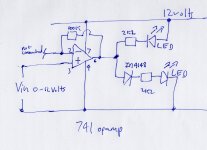
This will drive two LED's. As the input voltage (a DC voltage) goes from 0 to 12 volts the LED's light progressively one to the other. At 6 volts both are equally lit.
Thats a starting point for one of many possible LED drive options. So you need an amplifier stage in front of this that is scaled so that no signal to max level audio gives 0 to 12 volts approx. It doesn't matter if it clips at high level. So you might get away with one more opamp (have a preset for gain control) and by AC coupling the output, feed that into a rectifier/cap ino the LED driver.
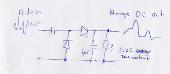
I've sketched an idea for the rectifier and "peak hold" that would go between the amp stage and the LED driver. You would have to experiment with time constants for best visual effect.
The 100K feedback resistor gives the option of adding "AC" gain to the LED driver stage later if needed (R and C to ground) or it can be linked out if not needed.
I show a 741 on 12 volts. Using lower voltages (if it has to be 5 volt) means choosing low voltage opamps.
Thats a starting point for one of many possible LED drive options. So you need an amplifier stage in front of this that is scaled so that no signal to max level audio gives 0 to 12 volts approx. It doesn't matter if it clips at high level. So you might get away with one more opamp (have a preset for gain control) and by AC coupling the output, feed that into a rectifier/cap ino the LED driver.
I've sketched an idea for the rectifier and "peak hold" that would go between the amp stage and the LED driver. You would have to experiment with time constants for best visual effect.
The 100K feedback resistor gives the option of adding "AC" gain to the LED driver stage later if needed (R and C to ground) or it can be linked out if not needed.
I show a 741 on 12 volts. Using lower voltages (if it has to be 5 volt) means choosing low voltage opamps.
Attachments
@ swissCHEESER
Hi, i'm not sure why you need 2 LED's ? Just one would "appear" to achieve more or less what you want.
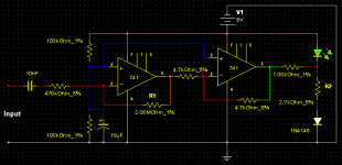
Expanding on Mooly's circuit i've simmed this. I made it to run off 9 Volts, as i "expect" this is likely.
Without a signal the LED will be lit, & as the signal increases it will flash more & more.
Adjust R1 for Input Level Sensitivity. Adjust R2 to set LED on Threshold.
Hi, i'm not sure why you need 2 LED's ? Just one would "appear" to achieve more or less what you want.
Expanding on Mooly's circuit i've simmed this. I made it to run off 9 Volts, as i "expect" this is likely.
Without a signal the LED will be lit, & as the signal increases it will flash more & more.
Adjust R1 for Input Level Sensitivity. Adjust R2 to set LED on Threshold.
Attachments
Mooly Circuit
Hey Mooly, I found some time to build your circuit. I put a quad op amp on the front side of it and am amping my signalup to 50 times with a 50k pot tied to a 1k to ground through a cap on the feedback. then into your circuit which i have the another 50k pot tied to a 1k to ground. In short, it doesn`t work.
If I plug the input into a guitar, both lights are dim. If I plug it into a preamp and my guitar into the preamp - it works to a certain extent, but doesn`t seem to get enough signal even with the preamp and 2500 times gain. I`m amplifying a signal that is roughly .01 to .100 milivolts from the guitar....should be well amplified to give some sort of result in the opamp. Not really sure what to do next other than pull some more hair out. Any ideas?
Mooly Circuit
Mooly, here`s a drawing of what I built. From what I understand of what you drew, I think this should work. Before I spend a few hours "debugging" this can you take a moment and look at it and see if perhaps I mis-understood or perhaps I have something completely wrong? About the only thing I`m sure of at this point is that what I built sure isn`t working. Thank you very much for your assistance and designs!
-swissCHEESER
An externally hosted image should be here but it was not working when we last tested it.
What is missing is the rectifier I mentioned. You have to change the AC (audio) into a varying "DC" quantity. Try adding the rectifier I drew after the first opamp. The resistor I showed with a question mark can be the lower 1Meg you already have (you might need to play around with values) The upper 1meg can also be altered. You have far to much gain too.
Try the rectifier first.
Remember I said it was just to get you started 🙂 Its not a fully worked and tried and tested design although the LED drive part definitely works as I described earlier.
Try the rectifier first.
Remember I said it was just to get you started 🙂 Its not a fully worked and tried and tested design although the LED drive part definitely works as I described earlier.
@ swissCHEESER
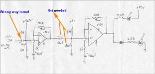
See my screenie for correcting the circuit you drew.
As you're using OpAmps now, try mine & see how it compares 😉
See my screenie for correcting the circuit you drew.
As you're using OpAmps now, try mine & see how it compares 😉
Attachments
Last edited:
Outcome until now
Thank you for your post ZeroD. I suppose the outcome is more hair pulling, and failure. I have built the circuit Mooly suggested...it doesn`t really work..for me anyways....took a long long time to build as well. I`m sure I`ve made some design failures...but gosh -- this is darned frustrating. I`ve spent the greater part of what feels like a year on this thing and reckon I might never get it to work.
Do you have any suggestions?
I`ve posted my schematic. Any time and expertise you would contribute would be greatly appreciated.
presently, when i plug in a quarter inch jack to the input and touch my thumb to the tip of the cable -- one light will dim slightly and the other will get a bit brighter....the tip of the iceberg to what i want. if i plug the cable into the guitar - i get virtually nothing unless i play really aggressively on the higher pitches. Seems like 33x gain, followed by up to 50x gain, followed by 33x gain should be enough to amplify the guitar signal enough to function with the last part of the circuit. But honestly, i have no way to check it to see if it is working. My oscilloscope is on the fritz and by Job, I am not sure what to do next.
does this circuit make sense to you? should it work? what parts of the circuit are faulty with respect to the design? how can i modify the circuit and get what i want? i want the two LEDs at the end of the circuit to respond to the input of the guitar dynamically. one should be on when the guitar is not being played -- the other one off. when the guitar is played the one which was on should dim (more or less, based on the dynamics of the signal) and the other LED should light up (more or less, based on the dynamics of the signal)
any ideas?
swissCHEESER
An externally hosted image should be here but it was not working when we last tested it.
ZeroD
ZeroD, all that jibberish at the end of my last post was an attempt to put in the blue bug-eyed smiley. results are par for the course. anyways, i wanted to chime in again to let you know that i tried the above schematic several times in circuit simulation before building. worked great of course. in the real world -- sure doesn`t...perhaps also par for the course. thanks for your help. -swissCHEESER
ZeroD, all that jibberish at the end of my last post was an attempt to put in the blue bug-eyed smiley. results are par for the course. anyways, i wanted to chime in again to let you know that i tried the above schematic several times in circuit simulation before building. worked great of course. in the real world -- sure doesn`t...perhaps also par for the course. thanks for your help. -swissCHEESER
You say it works in simulation but not in the real world.
Is the feed from the guitar suitable for driving the input stage as it stands ? What program are you simulating it in ?
I've deleted that last post 🙂
Is the feed from the guitar suitable for driving the input stage as it stands ? What program are you simulating it in ?
I've deleted that last post 🙂
suitable input
Mooly, I`m not sure about the input of the guitar....what should it be to be classified as suitable to drive the input stage? As for the simulation -- I used the java applet found at this website. Circuit Simulator Applet if you are up for downloading that applet, i can post the text file which you can import and see it working on a computer. the exact same circuit -- doesn`t function the same in the real world. ho hum.
Mooly, I`m not sure about the input of the guitar....what should it be to be classified as suitable to drive the input stage? As for the simulation -- I used the java applet found at this website. Circuit Simulator Applet if you are up for downloading that applet, i can post the text file which you can import and see it working on a computer. the exact same circuit -- doesn`t function the same in the real world. ho hum.
I wondered if it was LTspice you were using.
Isn't a guitar pickup high impedance ? That needs to work into a really high impedance.
Let me have a think and see what I come up with 🙂 I'm not keen on those on line circuit simulator do dahs 😀
Isn't a guitar pickup high impedance ? That needs to work into a really high impedance.
Let me have a think and see what I come up with 🙂 I'm not keen on those on line circuit simulator do dahs 😀
giutar pickup impedence
Mooly, thanks for putting some time and thought into it. Regarding the guitar...and the pickup output impedence....i measured the 1/4 cable when it was plugged into the guitar and get 3.8k ohms resistance....not sure if this equates directly to impedence. Anywho, online my preliminary research tells me it is normal to expect output impedence in the range of 6k to 10k from the normal passive pickup guitar. As for how that equates to the input impedence of the circuit....well...i have no idea.
Mooly, thanks for putting some time and thought into it. Regarding the guitar...and the pickup output impedence....i measured the 1/4 cable when it was plugged into the guitar and get 3.8k ohms resistance....not sure if this equates directly to impedence. Anywho, online my preliminary research tells me it is normal to expect output impedence in the range of 6k to 10k from the normal passive pickup guitar. As for how that equates to the input impedence of the circuit....well...i have no idea.
impedence
not even sure if i`m spelling that right...but if i wanted to raise the input impedence of my "amp" to allow for a better acceptance of the signal.... would it behoove me to swap out the 10k resistor on the input with a 100k..? and then swap out the 1nF cap on the input with a 100pF? hmmm....perplexing. not sure why that would make a difference....would it?
not even sure if i`m spelling that right...but if i wanted to raise the input impedence of my "amp" to allow for a better acceptance of the signal.... would it behoove me to swap out the 10k resistor on the input with a 100k..? and then swap out the 1nF cap on the input with a 100pF? hmmm....perplexing. not sure why that would make a difference....would it?
- Status
- Not open for further replies.
- Home
- Live Sound
- Instruments and Amps
- Stuck on Circuit Guitar Preamp LED mirror