Anything between 470K and 1M is a good value to use for the input impedance of a guitar circuit. You can go lower and higher, but this is the best range to go for with utility circuits like this. If you start getting close to 100K and below, it will begin to noticeably load the pickup down and decrease the high frequency response. Sometimes this can be exploited if a certain effect is desired, but for utility circuits, best to just stick to the 1M range.
For the input opamp, I'd use a TL062. Because it works well with the 1M impedance, and it's very low current draw. It's noisier than a TL072, but since it's being used to drive and LED circuit, I don't think you'll notice the noise.
I would strongly consider reducing the input impedance of the subsequent stages, especially if you'll be using 4558s for them. 1M is good for the first stage, but I'd initially start with around 100k for the subsequent ones.
Probably a good idea to try loading the output of the 10uF coupling cap with a 10k to ground before the rectifier diodes.
The 1nf cap will shunt a lot of the higher frequencies (reducing their amplitude), how much depends on the source output impedance. By all means try reducing or removing it.
If the guitar output impedance is 10K then that's not all that high in relation to your circuit. The 10K series input resistor isn't doing much tbh as it is swamped by the 1Meg and its really that 1Meg that is setting the input impedance of the first stage. You could even short the 10K out.
I'll see what I can come up with but it won't be today 🙂
No, leave it 10K. The 1M going to the virtual ground divider is what sets the input Z of a non-inverting amp as it is arranged here.not even sure if i`m spelling that right...but if i wanted to raise the input impedence of my "amp" to allow for a better acceptance of the signal.... would it behoove me to swap out the 10k resistor on the input with a 100k..?
@ swissCHEESER
I wondered where you were !
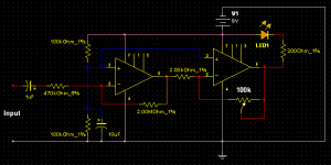
There's a Lot wrong with your latest circuit. But rather than go into it, try this one i've simmed. The LED is on with no signal, & flashes with more signal.
If your not happy after you've tried that, then i think the way to achieve what you want is 2 circuits working together. One would be an OpAmp configured as a comparator which would turn off an LED when it's triggered by a signal. Another OpAmp would flash in sympathy with a signal. Probably a dual OpAmp, or 2 x single, would do it.
I wondered where you were !
There's a Lot wrong with your latest circuit. But rather than go into it, try this one i've simmed. The LED is on with no signal, & flashes with more signal.
If your not happy after you've tried that, then i think the way to achieve what you want is 2 circuits working together. One would be an OpAmp configured as a comparator which would turn off an LED when it's triggered by a signal. Another OpAmp would flash in sympathy with a signal. Probably a dual OpAmp, or 2 x single, would do it.
Attachments
I'll draw it tomorrow for you... seem to be running out of time today 🙂
Its little different to what have actually.
Its little different to what have actually.
Thanks a Million!
Wow Mooly, I can`t wait to see it! Thank you so much for taking the time to build a working prototype. Let me know how I can repay you for the drawing. swissCHEESER
Wow Mooly, I can`t wait to see it! Thank you so much for taking the time to build a working prototype. Let me know how I can repay you for the drawing. swissCHEESER
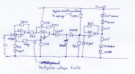
Here we go, Hope it makes sense. Opamps are 741
This is the exact circuit. Some values could be optimised but this works...
The 2v7 zener simply allows the green LED to extinguish fully (due to the 741 not being able to swing fully to each rail)
The 270K applies a little forwar bias to the opamp/rectifier output and improves sensitivity and response.
The 4.7uf cap (it is 4.7 the dots faint on paper) on the rectifier output can be as low as 0.1uf. Experiment to suit taste.
The two 6K8's generate the 6 volt reference. They can be a lot higher in value to save a bit of current.
No coupling cap between opamps 1 and 2 because the DC voltage on opamp output and the input of the following stage are essentially the same.
The 82K feedback resistor on opamp 3 was put there with the idea of adding gain but it didn't need it... but the option is there.
Attachments
The input impedance is high at around 1meg. I don't know what the output from a guitar pickup is but if you need more gain then you can drop the value of the two 5K6 resistors. And try the gain option on the final opamp.
Possible improvements. Using TL071 or TL081 opamps for opamp 1 and 2. The hf response of the 741 will be poor at such high gain but that doesn't matter to much since the guitar fundamentals are quite low.
Use high efficiency LED's and tweak the final resistors to get desired brightness.
Possible improvements. Using TL071 or TL081 opamps for opamp 1 and 2. The hf response of the 741 will be poor at such high gain but that doesn't matter to much since the guitar fundamentals are quite low.
Use high efficiency LED's and tweak the final resistors to get desired brightness.
Thank you Mooly
Wow Mooly, I am really excited to try it out and see if I can get it to work. Thank you so much for taking the time and energy (and brainpower) to put this together for me. Let me know if there is a way I can return the favor. swissCHEESER
Wow Mooly, I am really excited to try it out and see if I can get it to work. Thank you so much for taking the time and energy (and brainpower) to put this together for me. Let me know if there is a way I can return the favor. swissCHEESER
@ Mooly
Hi, i simmed your latest circuit & i'm pleased to say it definately seems to work fine, after a little tinkering. So congrats on that 🙂
The 2k7 resistors failed to light up the virtual LED's, so i swapped them for 270 Ohms, which did the trick. You did mention though using HB LED's, & they wouldn't need such a low value.
@ swissCHEESER
Hope you get it working 🙂
Thanks 🙂
Never heard of virtual LED's before 😀 True high brightness LED's can be to bright to comfortably look at even with just a few milliamps.
Never heard of virtual LED's before 😀 True high brightness LED's can be to bright to comfortably look at even with just a few milliamps.
Thank you Mooly
Hey Mooly, I had to order some parts and find the time to build the circuit you designed. Just finished - It works marvelously well! Thanks a million! What an amazing effort by you -- I really appreciate it. Sincerely, swissCHEESER
Hey Mooly, I had to order some parts and find the time to build the circuit you designed. Just finished - It works marvelously well! Thanks a million! What an amazing effort by you -- I really appreciate it. Sincerely, swissCHEESER
Thanks again Mooly
Hey Mooly,
Just wanted to let you know the circuit is still in use and I still really appreciate the effort you put in to design it. I never could have done it without your help. I am about to build another one just like the first. Looking forward to putting it together.
Many thanks,
swissCHEESER
Hey Mooly,
Just wanted to let you know the circuit is still in use and I still really appreciate the effort you put in to design it. I never could have done it without your help. I am about to build another one just like the first. Looking forward to putting it together.
Many thanks,
swissCHEESER
 Pleased to hear that its all working OK.
- Status
- Not open for further replies.
- Home
- Live Sound
- Instruments and Amps
- Stuck on Circuit Guitar Preamp LED mirror