Re: Are you using LT1085?
Hi Fabian,
Now that is some news!
I will order some LM317s too.
Regards,
Lucas
Hi Jax,
So this expensive LT1085 is pretty difficult ot handle...
I will try your solution too. If two persons point at the 1085 being the problem, it is worthwile to try this.
Thanks.
Lucas
Fabian said:Lucas,
I've also built Doede's dddac. In the beginning all I could hear was a lot of noise but almost no music. Quite similar to your description. It took me more than a day to find the problem: LT1085 just didn't work (although it measured well). After replacing with a LM317T it worked fine.
BTW: Doede recommends 3.85V, not 3.5V as you mentioned in post #6
Fabian
Hi Fabian,
Now that is some news!
I will order some LM317s too.
Regards,
Lucas
Jax said:LT1085 needs at least 150uF on the output if a bypass capacitor is used on the adjust pin. A 10uF is also needed on the input pin to ground since the distance to the source is significant. Else it may oscillate.
LM317 is more stable but noisier and need no capacitor at all on the output.
Hi Jax,
So this expensive LT1085 is pretty difficult ot handle...
I will try your solution too. If two persons point at the 1085 being the problem, it is worthwile to try this.
Thanks.
Lucas
jewilson said:You should be using a buffer somthing like a 74ACT244 to drive all those DACs. That's to much of a load on the 8412.
Also, check to make sure you have set modes M0,M1,M2, M3 correctly. The can change with different DACs.
Also, change filter cap on the 8412 to a .047uf film cap, don't use an electrolytic there.
Hi Jewilson,
It DOES work with 8 TDA's in Doede's own setup...

Lucas
finneybear said:Lucas, if the problem existed already when the DACs were cool, then I am running out of clue as well. Probably you just have to try the simple but dumb way... replace the parts one by one to see how it goes.
The Doede board looks good to me already. Yet if I have to make a new board myself, definitely I will add more buffers to the 8412 and reroute the ground.
The 4x2 idea goes this way: A is for the top, B for the bottom. The arrangement looks like: ABAB. This will ensure any two adjacent sets will always share one side to have the shortest signal path. Now I will have to come out a good way to connect the right signals together. Probably through p2p shielded silver wires? Another good thing about this topolgy is that there will be no signals go between the pins. I can put ground lines around them instead.
It will be easy to install heat sinks as well. Probably no need for a fan anymore.
Hi Finnybear,
Yes, I guess I will alaso have to exchange the 8412...

Desoldering the current one will be a nice job...
BTW, with the aluminium tower that I constructed, you can also get away without a cooling fan, as long as you attach some decent heatsinks (3 x 5 x 1 cm) on the sides of it.
Regards,
Lucas
Can you test the CS8412 on its own? If you have a LED connected to pin 25 it will go out when the CS8412 locks to the data.
ray
ray
Loading
Lucas_G
I do not know what the input impedance of the DAC looks like now, but you have severely reduced the input impedance by a bunch. Crystal has not rated the output current for the clock and data outputs on this part, however you should not be driving this many gates from the 8412, it is just a poor design practice to do that.
Next, issue with this implementation you are slowing the down both devices due to the load. This will reduce the rise time at the DAC's input and can make the converter more susceptible to jitter.
Try adding a buffer there; you might be surprised to here the difference. Also, ground the input to the unused gates.
It DOES work with 8 TDA's in Doede's own setup
Lucas_G
I do not know what the input impedance of the DAC looks like now, but you have severely reduced the input impedance by a bunch. Crystal has not rated the output current for the clock and data outputs on this part, however you should not be driving this many gates from the 8412, it is just a poor design practice to do that.
Next, issue with this implementation you are slowing the down both devices due to the load. This will reduce the rise time at the DAC's input and can make the converter more susceptible to jitter.
Try adding a buffer there; you might be surprised to here the difference. Also, ground the input to the unused gates.
Lucas, I am afraid that the heat is still a concern. The chip may be a bit cooler outside but the internal junction temerpature may be still too high. DAC chips performance is very sensitive to heat actually. Since I will redo the PCB, the new 4x2 arrangement will give me some edge on both heat dissipation as well as signal feed quality. I want to create a topology such that the signal paths from 8412 to the 8 1543 all have equal length. A buffer or two between them. The output of the reclock circuit is a concern, too.
finneybear said:Lucas, I am afraid that the heat is still a concern. The chip may be a bit cooler outside but the internal junction temerpature may be still too high. DAC chips performance is very sensitive to heat actually. Since I will redo the PCB, the new 4x2 arrangement will give me some edge on both heat dissipation as well as signal feed quality. I want to create a topology such that the signal paths from 8412 to the 8 1543 all have equal length. A buffer or two between them. The output of the reclock circuit is a concern, too.
Hi finneybear,
I will be very interested in such a redo of the pcb!
Maybe we should also consider to place 4 times 2 chips on the underside of the pcb. With alu strips between them, we could press the aluminium on to the bottomplate of the enclosure...
Regards,
Lucas
Hi Lucas,
The 1543s can not be all on the same side otherwise some signals will have to go between the pins. ABAB is still the best way to go, I think? Every two sets can still share one heat sink. A memory chip heat sink can do the job. I still have to sit down and think about a way to get equal signal path length. A tiny clock skew to different 1543, for instance, will have impact on the sound image, etc. Even the DAC tower solution has this problem.
The 1543s can not be all on the same side otherwise some signals will have to go between the pins. ABAB is still the best way to go, I think? Every two sets can still share one heat sink. A memory chip heat sink can do the job. I still have to sit down and think about a way to get equal signal path length. A tiny clock skew to different 1543, for instance, will have impact on the sound image, etc. Even the DAC tower solution has this problem.
Hi Lucas,
I see you are still trying to get your problem fixed....
Looking at all the reactions, you may be understand now, why I cannot give support from a distance..... I had one DDDAC1543 builder with the problem that nothing worked !! The solution was to remove a small splitter of metal on the datatrack !! There is no way you can find things like this through email.
I also noticed that your request for help post has also encouraged people to start proposing redesigns and tweaks, not to mention statements on how the dac is supposed to work and not work.... This is clearly not helping you and you seem not to have to the means to do so, which I regret. If you like you can send the DAC to me and I will fix it for you.
In the meantime: many builders have finished the dac and are very happy with the results, even with poor ground designs or cs8412 loads which are too high 😉 Don't get yourself distracted. The set up works fine and gives a much better result than the cost would justify....
Oh, I use the 1085 myself......... with 22uF Black Gate. The datasheet recommends this value (10-22). If you use a cheap electrolite, this might proof to be too low. so have you tried a 220uF (just to make sure) at the output from the 1085?
any way my offer stands.....
take care
doede
Hello,
I have problems as well:
When I put my dac tower in, the LT1085 does not hold his voltage, without dac tower I have the 8.5V, with dac tower it drops to 1.87V or so.
When I remove the dac tower and put in one dac, and change Rsource to about 2k and change Rref to get to 3.85V DC output I get a nasty osclillation of about 50Mhz 2v top-to-top on the output. However when I turn on my cd-player the dac works. When I turn down the input voltage (I run of a stabilized variable power supply instead of a battery) to about 8V (the LT1085 does not have to do anything anymore) the oscillation stops! And the line out looks nice! When I put the tower back in, everything stops, 1.87V on VA2, nasty oscillations on the power supply rail etc.
So there is something wrong with this LT1085 thingy! By the way I use dirt as sh*t 22uf 35V elco's instead of BG because the BG's are in backorder! I will raise the elco's to 100uf or so tonight...
Edwin
OK, I think I found the problem. It is 100% the LT1085....
When it starts cold, there is oscilation which can be heard as hard noise. In my DAC at home after a minute or so it is gone, I thought it was the DAC biasing and did not cared too much, as every thing worked fine after warm up. My tube amps have to warm up also, eh?
BUT, it might be, that in some other (critical) situations, the 1085 does NOT STOP making noise !!!
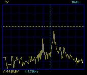
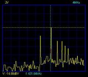
I have just measured it and just check the scope pictures....
Please do note the difference in scale !! When the warm up is done, the rest-noise is at an average of -90dB. This is ok enough, although I am sure some will diasagree, 🙄
The cold pictures show clear hard stuff !!!-15dB is not particulary a good noise floor level 😉
ANYWAY: try a larger C at the output of the 1085 or take a LM317.....
Will make notes at the WEB Site as well....
Take care
doede
When it starts cold, there is oscilation which can be heard as hard noise. In my DAC at home after a minute or so it is gone, I thought it was the DAC biasing and did not cared too much, as every thing worked fine after warm up. My tube amps have to warm up also, eh?
BUT, it might be, that in some other (critical) situations, the 1085 does NOT STOP making noise !!!
I have just measured it and just check the scope pictures....
Please do note the difference in scale !! When the warm up is done, the rest-noise is at an average of -90dB. This is ok enough, although I am sure some will diasagree, 🙄
The cold pictures show clear hard stuff !!!-15dB is not particulary a good noise floor level 😉
ANYWAY: try a larger C at the output of the 1085 or take a LM317.....
Will make notes at the WEB Site as well....
Take care
doede
Attachments

Ola said:Hi Doede!
I can't enter Your dac page, explorer crashes.
?
Best regards
Ola
I have a cheap WEB-HOST
some times there is no site....Should work ok in the meantime....
br
doede
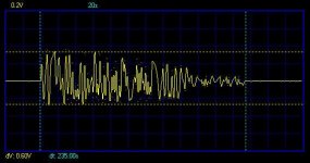
OK, last image on this issue..........
This is a time recorder of the output of the 1085.
After switch-on the oscillations start at aprox 0,6 Volt (!)
As time goes by, the oscillations start to decreas and suddenly disapear after aprox 235 Seconds.....
OK, 4 minutes warm up, never realized it is that much
for easy to copy DIY-stuff I may be had better not mentioned the 1085 as an "alternative" for the LM317, which is clearly more stable!
doede
Attachments
LT1085
Hi Doede,
This thread might be helpfull:
http://www.diyaudio.com/forums/showthread.php?s=&threadid=7265&highlight=
😎
Hi Doede,
This thread might be helpfull:
http://www.diyaudio.com/forums/showthread.php?s=&threadid=7265&highlight=
😎
I could not stop 😉
So close........., so I did some more checking. I tried a few capacitor values at the output and every thing above 40uF stopped the noises at cold start !!!
My suggestion: Increase the Value of the output C to 47uF - 100uF when a LT1085 is used..........
This can be done emperical of course as you can hear it, no need for scope 😀
I am glad as well, as now I have no "warm-up" time any more of 4 minutes.... hahaha !!
Regards
doede
Good finding, Doede. Now one less thing for me to worry about. Forgot to tell you that I got the board from you last week. Thank you. What a lovely board! The design is very good but now I am trying to see whether I can squeeze a bit more performance out it. 🙂
dddac said:I tried a few capacitor values at the output and every thing above 40uF stopped the noises at cold start !!!
My suggestion: Increase the Value of the output C to 47uF - 100uF when a LT1085 is used..........
I still have oscillations with my dac tower... I changed the C to 100uf (jamicon) and the output of the LT1085 ramped up to 5.5V instead of 1.87V and less oscilation (still a lot). Then I put a big 1000uf BG on the 12V voltage rails (for the record, I use a stabilized variable lab power supply for testing instead of an battery) and I get the 8.5V on the LT1085 but with an > 20Mhz oscilation with a top-top of 0.4V . Everything is working except for this oscililation.
This morning (had to test it before work! 😎 ) I still had some thoughts about my power supply and I changed it for a RC car 9.6V battery. Without the 1000uf BG on the voltage rails I still get a awfull lot of oscilcations. With the 1000uf BG I have the same picture as with my lab powersupply. 🙁
I just bought some 100uf, 220uf, 470uf C's and a lm317T to test more tonight...
So it seems that just ramping up the output C to 100uf is not the answer to everybodies problems 🙁
Nasty beast this LT1085...
Edwin
- Status
- Not open for further replies.
- Home
- Source & Line
- Digital Source
- Stuck as a Duck on the Doede Dac!