Fair point - yeah it's a tight space, but the counter logic is the chimney effect (which is supposedly what the cans achieve) and maybe some more ventilation holes from below would also be effective? I will use an IR temp gun and see what the plate measures which will be mostly radiated heat.
Counter logic 🙂 That is tube pilot lingo. For the chimney effect there should be free flow of air from underneath hence my suggestion to drill 6 mm holes. Risk is then that the holes will be filled with dirt and dust after a while hampering air flow. If it would be my device I would drill 6 mm holes in the lower portion of the right side metal plate and cut the left metal plate completely till about the upper valve as there are also conductors quite close to it. Good reasons to take it away and normal lifetime for the tubes as a bonus. Enough valid reasons to correct a construction error.
Which leads to the logic question WHY the tubes are located in a too tight shielded metal environment with insufficient air flow. One could look at it as a bulb that consumes 0.6 x 6.3 = 3.8W filament power and a maximum Pa of 2 x 3.5W. That is a bulb of around 10W. That 10W of heat needs to be given to the environment. There must have been a serious reason not to let that heat go to the environment. I have a hunch that the tube coolers did not improve matters in this particular case.
Which leads to the logic question WHY the tubes are located in a too tight shielded metal environment with insufficient air flow. One could look at it as a bulb that consumes 0.6 x 6.3 = 3.8W filament power and a maximum Pa of 2 x 3.5W. That is a bulb of around 10W. That 10W of heat needs to be given to the environment. There must have been a serious reason not to let that heat go to the environment. I have a hunch that the tube coolers did not improve matters in this particular case.
Last edited:
I agree coolers did not work :-(Counter logic 🙂 That is tube pilot lingo. For the chimney effect there should be free flow of air from underneath hence my suggestion to drill 6 mm holes. Risk is then that the holes will be filled with dirt and dust after a while hampering air flow. If it would be my device I would drill 6 mm holes in the lower portion of the right side metal plate and cut the left metal plate completely till about the upper valve as there are also conductors quite close to it. Good reasons to take it away and normal lifetime for the tubes as a bonus. Enough valid reasons to correct a construction error.
Which leads to the logic question WHY the tubes are located in a too tight shielded metal environment with insufficient air flow. One could look at it as a bulb that consumes 0.6 x 6.3 = 3.8W filament power and a maximum Pa of 2 x 3.5W. That is a bulb of around 10W. That 10W of heat needs to be given to the environment. There must have been a serious reason not to let that heat go to the environment. I have a hunch that the tube coolers did not improve matters in this particular case.
Just checked the plates of metal around the valve and they are about 5 Deg C more (35 DegC) than the surrounding plates which are around 30, the amp is generally around 25+.
The plate conducts heat through it like a pseudo heat sink and there is plenty of air on the outside of the plates.
My instinct/hope is that with the cooler removed the valve will be ok.
I also think the majority of heat loss from the valve will be convection, not radiation (feeling the air around valves in open surroundings confirms this) and the holes that surround the valve from the PCB below are around 5-6mm and will allow air to flow past the valve.
Correct engineering would mean you measure the tube temperature and not the metal plate as that one may be 100 degrees and still nothing would change as metal plates tend to be passive parts not caring about temperature. Instinct, hope and assumption are unknown parameters in engineering. There is no direct contact between the tube and the metal plates and the metal plates have a quite large surface so they will allow the radiated heat to the environment and won't heat up much. The tube itself does not get enough air flow and then it overheats. This was already a proven phenomenon as the glass cracked. The new tube likely will have the same fate. As stated in post 22 this situation is non standard and it leads to tubes going EOL too soon. The posed question was why this is made like it is as it is clear that it does not lead to success. You have the explanation, you could try to follow the reasoning of your own findings in post #15. If it helps, please look around and see how many devices are designed like yours.
Last edited:
noted, I am an engineer and so the logic is reasonably understood, the tube temp is impossible to measure with IR and I do have a sensor so I can use this, however I don't know what is 'normal' for this valve in this circuit with an unrestricted flow of air. I will do this though and record it.Correct engineering would mean you measure the tube temperature and not the metal plate as that one may be 100 degrees and still nothing would change as metal plates tend to be passive parts not caring about temperature. Instinct, hope and assumption are unknown parameters in engineering. If heat transfer would be optimal the metal plates would be hotter. As the tube does not get enough air flow the tube overheats. This was already a proven phenomenon as the glass cracked. The new tube likely will have the same fate.
You have the explanation, you could try to follow the reasoning of your own findings in post #15. If it helps, please look around and see how many devices are designed like yours.
The only way heat transfer occurs is through conduction, radiation, and convection. For the plates to get hot this will be local warm air conducting as it passes by and in my view mostly radiating in this orientation from the valve directly as the warm air needs to pass the valve first. The conduction of heat through air as a medium is not great. The plates will radiate heat back at the 35 Deg C like a warmer day would to heat local air. The base of the plates are above the PCB base by about 10mm so this should allow air to enter and I do believe there will be a beneficial chimney effect to an extent. It's a complex piece of fluid dynamics to be honest, but the very principle of those valve coolers is to help the valve air flow through a conduction and chimney effect, so the principle IF there is enough local air flow is sensible.
The deviation from normal situations is that the tubes are locked in a tight space and since one died from overheating and had a discolored tube cooler we simply know for sure that it does not get enough cooling. Whatever is believed/assumed and explained with counter logic 😀... the tube needs to get rid of its heat which it now obviously can not.
Last edited:
AFAIK there is no picture shown of the bottom and upper cover. If these are non vented well....then there really is no hope left I think.
It would help to solve issues in a logical sequence.
It would help to solve issues in a logical sequence.
Last edited:
Yeah both top and bottom fully open with mesh/grill the PCB has 6mm holes to allow airflow around the valve base.AFAIK there is no picture shown of the bottom and upper cover. If these are non vented well....then there really is no hope left I think.
It would help to solve issues in a logical sequence.
So the upper and bottom cover are OK and pose no issue. Then the old issue still stands. Denial is the first step to acceptance. There is a difference between "enough" and "not enough".
Good luck solving the issue.
Good luck solving the issue.
Last edited:
thanks for the advice 🙂So the upper and bottom cover are OK and pose no issue. Then the old issue still stands. Denial is the first step to acceptance. There is a difference between "enough" and "not enough".
Good luck solving the issue.
So for interest I measured the valve with a thermocouple, the 12BH7 gets up to 80 Deg C on the top, no idea how this compares to other installations of the same valve.
Oh - just to add a final conclusion to this conversation, and pose a question in relation.
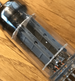
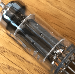
The 12BH7A was replaced with another valve (same model shown here) The additional enclosure limiting air flow was removed and the outcome of sparking in the valve base was the same after 6 weeks of 2 hrs use on some evenings with this brand new identical valve.
I then put in a NOS GE 12BH7A and it's been fine ever since, just like it was fine in the many yers prior.
A picture of the faulty valve is shown, along with some strange deposits/flecks of silver.
I think this is faulty valves, any experience of this type of failure?
Attachments
That looks like cathode coating or possibly coating off the heaters. Then & again it could be flecks of mica. I've used 12BH7A's in quite a few of my amps & never had this issue, mine are all NOS.
Andy.
Andy.
- Home
- Amplifiers
- Tubes / Valves
- Strange 'tick' or 'spark' noise on power up of valve pre amp - any ideas what it could be [it's not the valves noise]