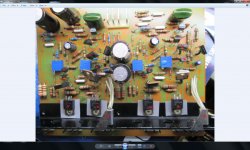
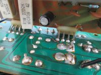
I connected 2 sets of 8 ohm speakers to my Sansui AU-11000 and it sounded very good,a few days later I was listening to it when I turned it off and back on about 20 minutes later but it wouldnt come out of protection so I took the speaker wires out pair by pair to see if it was the speakers and the very last pair of wires I took out had it come out of protection? I put the A speakers into where the B speakers had been and everything was OK. So the next day I thought Id better check the DC offset and bias settings.The DC offset was pretty close at around -20 milivolts. The bias was way out until I realized I had connected the DMM up wrong! So when I had just got it all done, I was withdrawing the screwdriver out and I touched something on the driver board with it and got a loud spark and bang. I checked the output transistors,they were OK but when I checked the transistors on the driver board 6 of them on each channel had their collector at a higher voltage than the emitter? I thought they were all blown at first but when I took them out of circuit and measured them,they were all OK? Ive checked everything on the board but cant find anything wrong? Its not connected to anything either. If anyone has any ideas or suggestions Im all ears.This has got me stumped? The red crosses mark the transistors with the strange readings,the others read normally.
Attachments
Bumpity Bump! Someone must have an idea of whats happening with this board? Any ideas and suggestions are welcome. Ive since then, found two blown PNP outputs to add to two blown fuses and a blown driver board transistor TR11 2SC735.
Attachments
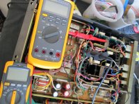
No I havent done that yet Jon,Ive got the amp powered on with a DBT because Ive just replaced all the output transistors with some pulled T0-3 MJ21194s and some bought T0-204AA MJ21193s at $10 each. I dont know what is going on with this board so Im being safe. I think you mean the voltage on the emitters of TR15 and TR16 that should read 1.2v? Ill put it back together,check it and let you know what it is?😀 Back again, the voltages read pos+1.162v and neg-1.075v with the amp powered on with the DBT.Ive set all the 25 turn VR pots to the middle,12.5 turns from the click at the end.
Last edited:
I just measured those transistors again with a different multimeter and they all read OK now? I still cant adjust the bias and DC offset though? I originaly had a problem with my multimeter not reading milli-amps so I bought a used Fluke 87v that turned out to be out of calibration, so I recently bought a $40 auto-ranging cheapy, thats the one I was using that gave bad readings on my driver transistors? So Ive gone in a full (expensive) circle and used my first DMM on diode setting.Now theres nothing wrong that I can find on the driver board but the bias and offset wont adjust? I live 500kms from Perth Western Australia so Ive got to find somewhere to calibrate this Fluke and post it to them any ideas?
I'm surprised you need calibration for repair work using a Fluke or any DMM above the $40 POS grade. It's a different world of $$$ when you talk calibration labs though. A recent cost for a DMM was a lot more than a new meter at $375 AU, not including return pack and freight. It's been that way for as long as I can remember as an NATA signatory for electrical testing wayback.
I suspect the testing problem is really that test current of a typical DMM is not enough to test the large semis correctly and you could need something like a curve tracer when checking out power semis properly anyway - at least pro audio technicians use them in one form or another because they are $$$$ if you buy the real deal. I used one of these for power semi. testing at home until recently - not ideal on the bench but a work-around for me to keep costs down: DY294 Digital Transistor Tester / Semiconductor Tester-in Other Measuring & Analysing Instruments from Industry & Business on Aliexpress.com | Alibaba Group
Note: A heatsink and external 6V power supply are needed for serious tests using this.
There are plenty of calibration service labs in the west - here's one at random that does multimeters - Flukes too but ask about your model for a quote first, You may be persuaded to buy rather than calibrate, depending on the organisation's attitude. Multimeter Calibration, Pressure Gauge to Thermometer Calibration Service
All the transistors on the driver board and output module read OK now! So I did a DC offset check,I read 2.5v on both channels with VR01 & VR02 set in the middle I adjusted the VRs fully clockwise until they clicked at 1,5v and the other side 1.8v, thats as far as it would adjust down? I took the measurements (before the relay because its in protection) from the metal bridge that joins the heatsinks together and speaker negative. All the DMMS read the same voltage. Could the differential transistors do this if they were out of spec? Ive actually got one of those DY294s it doesnt look like yours though, mine is a bare bones affair and I rarely get to use it because I cant test T0-3 transistors on it or test in circuit.I got a $140 quote to look at my Fluke not including $40 plus postage.
Attachments
I know its not that hard to search and download the manual but your slice of the PA schematic doesn't cover the relay protection circuit you refer to. Someone experienced with these might offer a little more help if you make it a little simpler for them with another section of the schematic or a link.
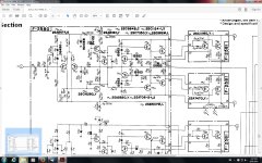
As it is, the offset adjustment range is limited by D01-4 diode voltages which should be checked for sensible readings and compared between channels, as should rail voltages and Vbe drops for each small signal transistor. ZD01 sets the +rail at the input stage to about 10V as a reference point. Note SV02 is a series pair of diodes setting the bias current from TR07 for TR05, the voltage amplifier. The schematic here is like a lot of contemporary Sansui amplifiers such as QRX 7001 receiver. Other threads for more common similar products may be helpful if you search them instead.
If your problem is the same in each channel though, you might consider how you are going about testing and what you may not follow if the same problems come and go each time you touch it. The amplifier itself is not a complex or unusual design and has been around for 40 years in one form or another. Measurements will be consistently good or bad unless you have bad electrical contact somewhere that results in wild voltage swings or your offset adjustments have flagged a fault current that caused protection to trigger accordingly.
Experience with IC based protection systems tells me that operation becomes erratic when the timing electrolytic(s) in the protection (relay?) circuit start to die - and they do with monotonous regularity in models where the small and usually cheap grade caps are close to heatsinks. This is a discrete circuit, common to both channels (meaning it responds to either channel faults) and chock full of 10 and 100-330uF caps. I would still check those out and just replace any low values with 105° types without wasting time fretting over maybes.
BTW, the transistor tester accepts TO3s or plastic power types directly via the top panel test sockets or with short plug-in leads as I use when a heatsink is needed. If you want to test power transistors properly, it's not a simple procedure to do in-circuit, unless you know the amplifier well and can work with and compensate for the voltages there. Otherwise, we need to remove and test in a standardized test jig - either commercial or DIY. Basic in-circuit tests for shorts, opens etc shouldn't be a problem anyway.
Note that the service manual is wrong - it has the idling current and dc offset VRs reversed!
Are you sure about that?
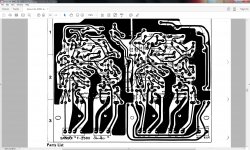
Ive found the problem,it was a blown grounding track on F-2567,the driver Power Supply board.I fixed it with an offcut from a capacitor lead.The reason I didnt see the blown track before was because it was tucked out of the way where I couldnt see it. I fired the amp up on a DBT and it came out of protection.Yay!!! Thanks for the ideas and suggestions fellas it all helps.
Attachments
Ive found the problem,it was a blown grounding track on F-2567,the driver Power Supply board.I fixed it with an offcut from a capacitor lead.The reason I didnt see the blown track before was because it was tucked out of the way where I couldnt see it. I fired the amp up on a DBT and it came out of protection.Yay!!! Thanks for the ideas and suggestions fellas it all helps.
Its my amplifier!
Oh bugger! When does it all end? lol I discovered an intermittent +32v B1 rail from the regulator/protection board F-2568 to F-2567 driver board,I found another broken track at the base of a pin near the last one.That explains some of the voltage readings I was getting. I fixed that and found that now I cant adjust the left dc offset below -134mv. It was -642mv! so Im wondering why the protection isnt cutting in? All the voltages seem OK although Im still on the DBT and they read lower than normal.The 1.2v test point on the schematic is +1.7v and -1,5v on the left channel compared to the right channel which is +1.1 and -.996v. Ive got no idea from here except to keep looking and testing? But where? Ive checked everything I can think of?
Fixed,Finally Whew! I went over the negative side of the driver board with a digital microscope (very interesting) and found another broken track at the edge of a transistor pin. Beautiful!
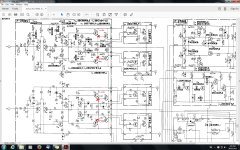
That wasnt it, its Not Fixed! I can adjust the DC offset but not the Bias? The meter wont move past 0.004mv on both channels. Ive checked every component on the board,done a continuity test on every track and replaced any resistors even slightly out of spec. Ive replaced the 2SA847 differential transistors with new ones.The electro capacitors are audio types and not that old,Ive checked them with a proper capacitor meter. The only voltages I can see that are out of spec are the emitter test points that are supposed to be 1.2v. I cant work out why they are out of spec and whats causing it? I still have the amp on a DBT so the test point emitters should read about 1.1v if it was correct? Pins 17 and 10 going to the relay on the driver power supply board are -285mv (pin 17) and +000.7mv (pin 10). Heres a schematic with the voltages. The amps coming out of protection when I turn it on.
Attachments
Last edited:
Make sure you're turning the correct VR. The one near the input stage is for DC offset adjustment. The service manual has the adjustment procedure in reverse.
Make sure you're turning the correct VR. The one near the input stage is for DC offset adjustment. The service manual has the adjustment procedure in reverse.
I wish it was that easy mate but youre wrong about that. Have a look at the the schematic I posted, it matches up with the bias VRs 3 and 4?

Last edited:
Is the bulb of the limiter contiuing to glow after settling? If only faintly, it's probably reasonable to test without it now, and check those voltages again. They will vary with bias level and probably according to predriver and driver transitor Beta, since the 1k base resistors R37,38 mean the whole bias spreader arrangement is unbalanced until the correct current is set, I guess.
There is a nominal 2V rail offset, so I'm not sure what difference there should be, if any, between those bias voltages.
Vbias of the driver and output stages should be around 4 x diode drops or ~2.6V total. You have ~ 2.3 and 2.7 which isn't so bad even if unenevenly spread. I think there is still a problem there, perhaps as you do. Hopefully reoldering will find it, assuming all the semis are still fine by Vbe checks etc.
Soldering failures are still dogging you and they'll continue to, until you systematically reflow them on the power amplifier boards at least. Inspection by microscope might be interesting but until all joints are reflowed, you can't be certain you have found them all. It might sound like a chore but it's got to be quicker and less agony than finding them one by one 😉
I almost killed mine when I followed the service manual. Luckily I was using a dim bulb tester. I know more people who have had the same issue due to the faulty service manual. Maybe some examples have been corrected, such as yours.I wish it was that easy mate but youre wrong about that. Have a look at the the schematic I posted, it matches up with the bias VRs 3 and 4?
- Status
- Not open for further replies.
- Home
- Amplifiers
- Solid State
- Strange Sansui Driver Board Problem?