I have http://i01.i.aliimg.com/img/pb/870/025/527/527025870_432.jpg
and http://i00.i.aliimg.com/img/pb/871/025/527/527025871_281.jpg
And I'm wondering if I can make a simple transistor amplifier out of either just one of these. or using both for a push-pull transistor amplifier
For audio use. I'm not sure how to even begin since I don't know how to connect multiple transistors together for a push-pull amplifier
So far I've only gotten a single transistor amp that works decently but uses way too much power and wastes some and generates a lot of unnecessary heat
The frequency response is very good but it distorts easily since it can't reach a good output
I can say I managed to make a single transistor amplifier that managed to pump a full 12" subwoofer a quarter of an inch or more in a large ported box using only a 12 volt 2-2.5 amp current power supply that was meant for an internet router
That actually moved the sub quite a load but sounded muddy and overheated really quickly to the point the heatsink was hot and the power supply needing to be unplugged
I'm wondering what values of resistors I would need if I were to put these two transistors together for a stupidly simple push-pull amplifier. If that's even possible
I'm not sure which one is pnp or npn so I need to figure that out first
There's a lot more to an amplifier than just a couple of transistors.
Might I suggest that you have a read of Rod Elliots site, it is a good place to start learning.
ESP Projects Pages - DIY Audio and Electronics
Might I suggest that you have a read of Rod Elliots site, it is a good place to start learning.
ESP Projects Pages - DIY Audio and Electronics
Last edited:
I'm not sure which one is pnp or npn so I need to figure that out first
B is PNP, D is NPN.
Aka, the KTB778 device is a PNP type, and the KTD998 is NPN.
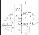
Those output devices would work in this very clean simple little amp. 😉
But do learn what Bias means as it needs to be set in this design.
jer🙂
But do learn what Bias means as it needs to be set in this design.
jer🙂
Attachments
Last edited:
And how can the bias across the diode stack change?
It's a sub amp, remove one diode and let it run class B.
Better yet, run a couple of emitter resistors on the drivers to the output section, run three diodes, and call it class AB+B. Add some emitter resistors to the outputs, maybe some base resistors too, and maybe base resistors on the drivers, and a small resistor on the IC out lead.
Hi,
Your flogging a dead horse trying to talk any real
circuit details with the OP, he's just not interested.
However any circuit has to be simple, AC coupled
(run off the 12V supply) and with enough details
to be totally idiot proof, which is a tall order.
rgds, sreten.
Your flogging a dead horse trying to talk any real
circuit details with the OP, he's just not interested.
However any circuit has to be simple, AC coupled
(run off the 12V supply) and with enough details
to be totally idiot proof, which is a tall order.
rgds, sreten.
Last edited:
djk,
Yes it would be good to add some emitter resistors but I didn't have any handy at the time, so I didn't employ them.
The bias is adjusted with the 20K pot R6 using an ammeter in series with one or both of the collectors and the power supply.
I forgot to mention that the schematic doesn't give the exact percent ratio for the setting of the R6 20Kpot either.
But I can assure you that this schematic works as is, and, was drawn directly from the actual working circuit that I had on my protoboard.
It was not just for subs and it worked great for the full range of the audio band.
I ran this circuit through it's paces and used output loads as low as 2 and 1 ohm and it worked as expected using a supply that has an ample current potential.
Not a lot of power but good enough to drive any quality speaker with very good sound.
I had as much as 1 amp to as little as 10 ma of bias flowing through the output transistors.
It had maximum of only 10ma or less of bias current offset at any setting and stayed balanced with no change in the current offset at any stetting.
The output offset voltage (Vos) was that of the opamp that used, typically less than 5mv or better.
All of the devices were very closely matched as is right out of my junk box.
I had already posted this circuit before in another discussion but I couldn't find the thread.
I had though about using just three diodes but I never tried it.
Since they are in a darlington configuration they needed more Vbe than what one diode would create.
So, I just used 2 of them for each the top and bottom to keep everything symmetrical.
I also had matched up the diodes Forward voltage drop (Vfr) of each pair so that they were equal for both halves.
sreten,
Good point but it was worth a try to give a little incentive with a simple circuit to help him learn more about how power amplifiers really work.
Else he is just looking to burn up his speaker and transistors or both.
This circuit can be configured for a single end AC output only amplifier as well very easily as I have tested it in that configuration too.
That is what the extra 4.7K resistor R10 and capacitor C3 was for on the +input to the opamp and all I had to do was add a 4.7k resistor to V+.
Then move the signal source input, if one choose too, or just leave it there.
And of course also add a output capacitor.
But this configuration does require a V+ and a V- power supplies.
FWIW
jer 🙂
Last edited:
Simple circuits have been presented to the OP in the past. Until he can read a schematic the cause is lost. Just do a quick search and it will become apparent what kind of tree you are barking up.
Hi,
The circuit is pretty much totally irrelevant in the context
of what the OP is after so there is no point arguing the
toss about it in this thread, lots of it are arguable.
Fails on requirement 1) to run off a 12V DC supply.
rgds, sreten.
The circuit is pretty much totally irrelevant in the context
of what the OP is after so there is no point arguing the
toss about it in this thread, lots of it are arguable.
Fails on requirement 1) to run off a 12V DC supply.
rgds, sreten.
Quote~"That actually moved the sub quite a load but sounded muddy and overheated really quickly to the point the heatsink was hot and the power supply needing to be unplugged"
Yes, I have been there with the OP several times before.
I can't see anything else that could be done with just a pair if transistors and a few resistors and 12v supply except to burn them up and expect it to sound muddy. 😉
Well so be it!!
Cheers!!
jer 🙂
Yes, I have been there with the OP several times before.
I can't see anything else that could be done with just a pair if transistors and a few resistors and 12v supply except to burn them up and expect it to sound muddy. 😉
Well so be it!!
Cheers!!
jer 🙂
Last edited:
Hi,
Well FWIW you can make a crude class A amplifier out
of just that pair, with some caps and resistors, driven
by a headphone output, similar to basic MC head amps.
Class AB can be done with another two small
transistors, and a few more other bits too.
rgds, sreten.
Well FWIW you can make a crude class A amplifier out
of just that pair, with some caps and resistors, driven
by a headphone output, similar to basic MC head amps.
Class AB can be done with another two small
transistors, and a few more other bits too.
rgds, sreten.
Last edited:
Something like this? I think he has a heatsink....you can make a crude class A amplifier out
of just that pair, with some caps and resistors, driven
by a headphone output...
Attachments
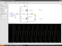
Here is another very very simple amp that I just whipped up in CircuitMaker that may work as well.
The green trace shows a peak of 1 amp through the 4 ohm load.
And the yellow trace shows the voltage across the 4 ohm load.
The gain voltage Gain of this circuit is less than one at 3.71Vp/5Vp= Vgain .742
Although the voltage gain is low the current gain at 10X is high enough to drive a speaker when driven from a headphone amp.
I used small signal transistors for the model, but should work just the same using the Power transistors as stated.
The 100 ohm resistors should be rated for at least 1 watt.
Make sure that you use a heatsink on the transistors as well as they will be dissipating some heat.
jer 🙂
Attachments
Last edited:
Just use the output pair in the power supply pins of a high-current opamp, an output cap, and you're done.
Nope, I drew it in a simulator, but didn't bother to run it. 😱 I'll try that now.Godfrey have you verified your circuit in a simulator?
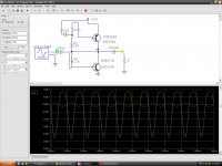
That's about what I expected. Distortion will be bad with more than about 10 or 20 mV input. It could be worth adding a resistor in series with the input - say 100R to 1K. That will reduce gain but should give less distortion for the same output. Alternatively, a resistor of one or two Ohms could be added in series with the emitter of the NPN transistor, for the same effect.Just curious becuase I just tried in in Circuitmaker and it does work with some nice voltage gain but it is very nonlinear.
Here's some results. I don't have the right transistor models, so I used some other power transistors instead, but it should give an idea.
Transistor idling current is only about 125mA or so, depending on the transistors, so output voltage is very limited, but increases with higher load impedance (see third pic). The output impedance is high too, so with normal speakers there'll be quite a bit of bass boost. 😀
Transistor idling current is only about 125mA or so, depending on the transistors, so output voltage is very limited, but increases with higher load impedance (see third pic). The output impedance is high too, so with normal speakers there'll be quite a bit of bass boost. 😀
Attachments
- Status
- Not open for further replies.
- Home
- Amplifiers
- Solid State
- Strange problems with transistors