Hi there.
I have the following situation:
- an williamson amplifier with 6p3s final tubes
- initially the amp was built with 2 small output transformers without ultraliniar windings but latter I decided to replace them with bigger ones (also having UL)
- I had to change the box (the new transformers are 4 times bigger) and to rewire everything
- in the end everything was fine excepting for a low hum not very disturbing but still audible
- I tried few things including changing the wires or movement of the power transformer outside the box only to see if a wrong positioning was the cause: the hum was still there no matter what
- I must mention I used a star ground pattern
- I went to a friend who has an oscilloscope and we made some measurements: we found a very high frequency (around 1 megahertz)!! The oscilloscope was an old Tesla one so we didn't had to much measurement possibilities (like harmonics).
What do you think should I try? Maybe there are not much info, please ask if something is not clear.
thanks a lot!
Oscillation can sometimes happen with UL. If not already present, try adding grid stoppers to the output control grids. Then g2 stoppers (say, 470ohms or 1K 2W wirewound). Finally, you may have to add snubber networks from each anode to g2.
Try disconnecting the global feedback until you are sure everything is OK without it.
If stable without GNFB you may need to tweak the feedback loop, or some other FR compensation to get it stable with feedback.
The Williamson can sometimes be tricky to get right.
Svein
If stable without GNFB you may need to tweak the feedback loop, or some other FR compensation to get it stable with feedback.
The Williamson can sometimes be tricky to get right.
Svein
1MHz oscillation is unlikely to be due to the global feedback loop. More likely to be local feedback in the output stage due to parasitics in the OPT.
However, disconnecting the global loop is a good debugging technique as it stops interactions complicating things.
However, disconnecting the global loop is a good debugging technique as it stops interactions complicating things.
Williamson Amp Stability
I'd look for possible ground loops but star ground really should prevent it. I had to increase my power supply cap ( double the size) to rid me of a very low level hum to a totally inaudible level.
If it is a circuit instability, try to jumper 1,000 pf to the input pins of the tubes and see if the hum still exists. Move to the next input etc... This should force a dominant pole into the k-hz range and stop high frequency oscillation. If it works, you know the area of the circuit to investigate. (without the global feed back) Just thinking, could you have connected the output feed back inverted?. Does it get louder of quieter with the global feedback?
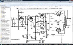
In the attached schematic R7, C5 create the dominate pole for Amp's stability. The capacitor can be increased for stability but excessively large with decrease the power bandwidth.
I'd look for possible ground loops but star ground really should prevent it. I had to increase my power supply cap ( double the size) to rid me of a very low level hum to a totally inaudible level.
If it is a circuit instability, try to jumper 1,000 pf to the input pins of the tubes and see if the hum still exists. Move to the next input etc... This should force a dominant pole into the k-hz range and stop high frequency oscillation. If it works, you know the area of the circuit to investigate. (without the global feed back) Just thinking, could you have connected the output feed back inverted?. Does it get louder of quieter with the global feedback?
In the attached schematic R7, C5 create the dominate pole for Amp's stability. The capacitor can be increased for stability but excessively large with decrease the power bandwidth.
Attachments
Thank you all for your ideas and suggestions. Next week I'll go to my friend again (I let the amp there) to try some things especially with the feedback. I'll let you know the results.
thanks again
thanks again
So, we did the following:
- changed the resistor in the NFB from 10k to 20K => the hum was louder
- changed the resistor with a potentiometer and try to obtain minimum audible hum => the new value is 2k5
- view on the scope: the now hardly audible hum still has high frequency component with about 200mV amplitude; rotating potentiometer changed the noise level but also cahnged the frequency
-disconnecting the global feedback only bring more noise
- we didn't changed the feedback capacitor value
I wonder there is no way to cut completly that noise. What else sgould I do?
thanks
Disconnect the coupling caps from the driver stage and jumper them to ground. Does the output still have the instability? If it does, then it is a combination of the bias and output tubes. Also disconnect the GNFB and look at the output of the driver section.
With the input grounded, it should be quiet.
The GNFB was trying to overcome it, just need to find the source.
With the input grounded, it should be quiet.
The GNFB was trying to overcome it, just need to find the source.
The feedback resistor reduces the hum simply by reducing the gain. It doesn't solve the problem, just hides it.
Can you sketch an exact diagram of your star grounding? It could be charging pulses getting into the audio. This only needs one wire connected to the wrong place, which could be very close to the right place!
Can you sketch an exact diagram of your star grounding? It could be charging pulses getting into the audio. This only needs one wire connected to the wrong place, which could be very close to the right place!
is this a 60hz hum or 120hz hum, or a wining noise?
do you have a 2 prong or 3 prong power cord on your amp and power amp? don't know why, but sometimes hum is caused by using a 3 prong cord in the amp or even preamp. I chased many ghost thruout many power amps, only to find the noise did not originate in the amp. for testing purposes, you could down convert a 3 prong, to a 2 prong using that grey plug addatper with the green wire.
another hum ghosts was scared off by changing driver tube type....had 12aT7's, put in 12hb7's, had 6414's, put in 6829's, etc.
also, have you tried metalized film by-pass capacitors? the frequency you are talking is uneffected by eletrolytic capacitors, you need a small value metal or poly film cap.
good luck, keep us posted
Hum is very much affected by electrolytics. It is unaffected by small value bypasses - whatever they do is at much higher frequencies.
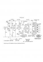
Oscillation can sometimes happen with UL. If not already present, try adding grid stoppers to the output control grids. Then g2 stoppers (say, 470ohms or 1K 2W wirewound). Finally, you may have to add snubber networks from each anode to g2.
Confusing ? See pic.
The principle applies whatever the poweramp rating esp when the UL tap is a greater part of the primary. In UL designs using high gm tubes and wide bandwidth transformers which may appear stable without this Zobel, there are other advantages in implementing it.
richy
Attachments
Sorry for this long silence. I take back home the amplifier, so no more Mr. Oscilloscope! I tried again with the old transformers (those without UL) and ... the hum wasn't there anymore! So I tried with the new OTs but using this time the same penthode mode and miracle! the hum disappeard! I must recognize I didn't try putting snubber networks as DF96 told me but I had grid stoppers in g2. Now I am in penthode mode and I have some other problems with anodic current but tonight I'll put some bigger values for those potentiometers in the negative bias area. Now I know the amplifier could be dead-silence. I still have some doubts: penthode, triode or UL? Anyway, I let know about the results.
thanks again.
thanks again.
Last edited:
Sorry for this long silence. I take back home the amplifier, so no more Mr. Oscilloscope! I tried again with the old transformers (those without UL) and ... the hum wasn't there anymore! So I tried with the new OTs but using this time the same penthode mode and miracle! the hum disappeard! I must recognize I didn't try putting snubber networks as DF96 told me but I had grid stoppers in g2. Now I am in penthode mode and I have some other problems with anodic current but tonight I'll put some bigger values for those potentiometers in the negative bias area. Now I know the amplifier could be dead-silence. I still have some doubts: penthode, triode or UL? Anyway, I let know about the results.
thanks again.
Get that scope back again and examine the output stage....Tell-tale signs.....My guess is if anode current varies for no other reason, then output stage is oscillating into HF.......Do Not connect speaker, use a dummy load instead.
richy
The scope was an old, huge Tesla and the friend don't have a high voltage probe.
Anyway, good news: I think I have a resonable hum. I'm sure it's induced by power transformer. But! If I connect only one RCA input connector. If I connect both, then the noise goes a bit up only in one channel. Somehow there is a ground loop that get closed through the signal cables, right in the cd player. But why is it humming only one channel? Another strange thing on the other channel: even if the volume is at minimum there I can stil hear the music playing on cd (very very low level, but it's there). Just to have the entire picture: yesterday I had another strange situation - slowly turning the volume, at one point there was a small crack noise only in one channel and the anodic current was going nuts: on that channel by doubling (from 45 to 100 mA) on the other channel dropping from 45 to 35 mA. I changed the value of NFB resistance from 10k to 30k and this behaviour ends.
I made a primitive sketch of my cables connection, I can't attache it.
Thanks.
That 'sounds' like an ultrasonic oscillation around the global feedback loop in one channel.
You now need to adjust the compensation to get it stable. A capacitor across the feedback resistor, with or without a resistor in series, and/or a lead-lag CR network at the inout stage anode. The circuit shown in post #13 has both of these, but you need to adjust the values to suit your circuit/OPT/layout.
You now need to adjust the compensation to get it stable. A capacitor across the feedback resistor, with or without a resistor in series, and/or a lead-lag CR network at the inout stage anode. The circuit shown in post #13 has both of these, but you need to adjust the values to suit your circuit/OPT/layout.
That 'sounds' like an ultrasonic oscillation around the global feedback loop in one channel.
You now need to adjust the compensation to get it stable. A capacitor across the feedback resistor, with or without a resistor in series, and/or a lead-lag CR network at the inout stage anode. The circuit shown in post #13 has both of these, but you need to adjust the values to suit your circuit/OPT/layout.
You mean by 'that' the strange modification of the anodic current? If so, then this is solved (I hope) after modifying the value of NFB resistor (as I said).
Now the problem is with that ground loop. I read this post http://www.diyaudio.com/forums/tubes-valves/167617-help-ground-hum-4.html and I'll try to do the same.
About the other thing with the sound keep going even with the volume at minimum, I think I must check the potentiometer maybe is something wrong there.
The change in the NFB resistor will have increased the voltage gain by about 3, which may or may not be what you want. You will get a bit more distortion and a narrower bandwidth, but better than oscillation!
Some volume pots don't quite go to zero at the bottom, but it could be a grounding problem.
Some volume pots don't quite go to zero at the bottom, but it could be a grounding problem.
The change in the NFB resistor will have increased the voltage gain by about 3, which may or may not be what you want. You will get a bit more distortion and a narrower bandwidth, but better than oscillation!.
Maybe I should try with something like 20K.
Some volume pots don't quite go to zero at the bottom, but it could be a grounding problem.
I tried another pot with the same result. So it's a grounding problem... but where? What do you suggest to look for? I really don't have the nerve to start again.
On the other hand now I only have the induction hum from the power transformer... it start immediatelly after powering on and remains the same. I did what Tom suggested at page 4 in http://www.diyaudio.com/forums/tubes-valves/167617-help-ground-hum-4.html and apparently that was all.
Thanks!~
- Status
- Not open for further replies.
- Home
- Amplifiers
- Tubes / Valves
- Strange hum in a Williamson amp