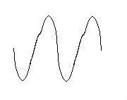
My latest breadboard experiment (triode wired, Class A1, 6CA7 PP) is exhibiting some strange distortion at high frequencies (the onset starts around 20-30kHz)The rising slopes of the sine wave have a wiggle, but the falling slopes look ok. Kind of looks like this.
The distortion increases with amplitude and also increases as frequency goes higher. Adding feedback makes the onset of the distortion occur sooner. The compensation scheme or values used when the loop is closed seem to offer little or no change in this regard.
Any ideas what is going on here? Some kind of OPT limitation? I've never seen this on my previous builds.
My latest breadboard experiment (triode wired, Class A1, 6CA7 PP)
I think your description of the circuit is a little brief.
Schematics and scope traces at all audio stages would help 😉
Sorry, I thought someone would recognize this type of distortion right off the bat. I'll post some more details when I get a chance. Right now, the schematic is in my head. Each channel is pretty much 2; 2-stage SE amps strapped back to back via input and output transformers. The output stage is cathode biased 5k plate to plate load, 380V B+. The driver of each 6CA7 is 1/2 6BN11 wired triode common cathode. The phase splitting is done by the input transformer.
The signal coming from the drivers looks clean, but I should probably check for any kind of phase error or change in amplitude difference between the two halves. However, it seems like a transformer parasitic causing the problem.
The signal coming from the drivers looks clean, but I should probably check for any kind of phase error or change in amplitude difference between the two halves. However, it seems like a transformer parasitic causing the problem.
Last edited:
Sorry, I thought someone would recognize this type of distortion......However, it seems like a transformer parasitic causing the problem.
I have seen distortion like this and it went away when I swapped the OPT's. Does the maximum power output drop at high frequencies too? Mine did.
Turns out that there is a phase shift going on between the two driving signals.
They are 180deg out of phase (as is desired) for frequencies below 20kHz. But once it hits about 20kHz, one of the signals phase starts shifting earlier than the other.
Tracked this phase shift down to the input tubes grid. So it seems the input capacitance of the two sections on the input tube is significantly different (a look at the 6BN11 suggests this may be plausible). Or there is some kind of imbalance between the two halves of the input transformers secondary.
Last edited:
Turns out that there is a phase shift going on between the two driving signals.
They are 180deg out of phase (as is desired) for frequencies below 20kHz. But once it hits about 20kHz, one of the signals phase starts shifting earlier than the other.
Tracked this phase shift down to the input tubes grid. So it seems the input capacitance of the two sections on the input tube is significantly different (a look at the 6BN11 suggests this may be plausible). Or there is some kind of imbalance between the two halves of the input transformers secondary.
Both are quite possible.. And I suspect in practice this might not be that much of an issue.
You might be able to pad up the input capacitance on the lower of the two sections with a gimmick between the grid and plate (grid and ground?) if you suspect that might be the cause.
Last edited:
You might be able to pad up the input capacitance on the lower of the two sections with a gimmick between the grid and plate (grid and ground?) if you suspect that might be the cause.
Thanks for the suggestion. That's what I'll try to do when I get a chance. It's a little surprising this type of issue isn't more common. There are a lot of "balanced" designs floating around out there.
If you have two input transformers then there is no reason why their HF resonances will coincide. Same for output. Near resonance you get a very rapid phase shift. This is why people normally use one combined transformer for both phases.
If you have two input transformers then there is no reason why their HF resonances will coincide. Same for output. Near resonance you get a very rapid phase shift. This is why people normally use one combined transformer for both phases.
I'm using 1 input transformer with a center tapped secondary. It's serving as a phase splitter.
Last edited:
Ok, I misunderstood. It could be stray capacitance then. Was the transformer intended for phase splitting? i.e. are the two secondaries tightly coupled?
Ok, I misunderstood. It could be stray capacitance then. Was the transformer intended for phase splitting? i.e. are the two secondaries tightly coupled?
Well, it is an inter-stage audio transformer with CT primary and secondary so I would think yes. But in practice, it seems like no.
Some testing last night indicates that it is the culprit of the phase-errors. I checked it out of circuit working into a resistive load using a matched pair of scope probes. There is significant phasing errors in the HF. I also checked it in-circuit with the tubes lit up, vs off. There was very little difference between the two. So it seems the tubes input capacitance isn't significantly contributing to the problem.
The input transformer also seems to behave dramatically different between signal source earthed vs. floating as well as if I swap the polarity. It also behaves dramatically different with secondary CT earthed vs. floating, but tied to the center of the load.
I found 1 wiring combination which is good enough to make the distortion on the amplifier output visually disappear, but I'm sure the measured THD would still be taking a turn for the worse as frequency increases. Since there is still some phasing errors if I check further up in the circuit. I'm probably just going to ditch the transformer phase splitter idea all together.
Last edited:
There will always be some variation of stray capacitance for different windings, but a good transformer will minimise these by winding in sections and interleaving. Was it intended for full-range audio use (i.e. hi-fi), and priced accordingly?
Are you using this transformer with source/load impedance somewhere near what the designer intended? Capacitance will be more important if your impedance is too high.
Are you using this transformer with source/load impedance somewhere near what the designer intended? Capacitance will be more important if your impedance is too high.
There will always be some variation of stray capacitance for different windings, but a good transformer will minimise these by winding in sections and interleaving. Was it intended for full-range audio use (i.e. hi-fi), and priced accordingly?
Are you using this transformer with source/load impedance somewhere near what the designer intended? Capacitance will be more important if your impedance is too high.
It is a budget hi-fi transformer (edcor WSM). Performance seems good used in single phase operation, but not as a phase splitter.
load impedance is on par, but source impedance is much lower than the reflected primary impedance. It's my understanding that transformers are supposed to perform better driven by a low source impedance assuming the secondary is terminated into the proper load.
Last edited:
I am not familiar with Edcor components, but their website tells me that WSM transformers cost $10. My guess is that they are intended for guitar or PA audio, not hi-fi. I would be surprised if anyone can make and sell a proper interleaved audio transformer for $10.
Vaguely similar items from Sowter in the UK cost £70 (=$100?). Now Sowter are known for being pricey (and good), but I think you need to pay more than $10.
Vaguely similar items from Sowter in the UK cost £70 (=$100?). Now Sowter are known for being pricey (and good), but I think you need to pay more than $10.
I guess the lesson learned is that if you can't afford Sowter, Jensen or something similar, then transformer based splitters are not the way to go.
Yes, with transformers you get what you pay for, more or less. Other components don't have this problem; the difference between 'ordinary' and 'expensive' parts is usually quite subtle (or even, perhaps, imagined in some cases). So the moral of the story is: either pay out for a good transformer, or manage without one. Sorry!
Interesting update: if I feed the input signal to the primary CT rather than the + terminal the phase errors go away as did the square wave overshoot & ringing on the amplifier output 🙂
I measured DCR to verify that it is indeed the CT and not a mis labeling.
I measured DCR to verify that it is indeed the CT and not a mis labeling.
That's interesting. It must shift the phase relationships of the internal capacitances just enough to overcome the problem.
- Status
- Not open for further replies.
- Home
- Amplifiers
- Tubes / Valves
- Strange HF distortion