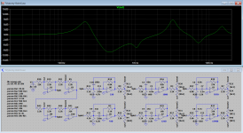
One issue you may have if the circuit is powered by a single 9V battery is that large boost at 220Hz eating all your headroom and causing clipping. If possible I'd use two batteries in series for 18V supply. And of course if you want reasonable battery life, low power opamps, given the number of them you need. I'd probably go with a couple of quad TLE2064 and one dual TLE2062, which will also handle well the heavy loads in some parts of the circuit. Then use 50k trimmers instead of pots and the pcb will be as compact as it can be, while still being adjustable in case it needs fine-tuning later.
Also the circuit as shown has an input impedance of 2k2 but active pickups like to see a 25k or so load, you can simply replace the input resistor (R20) and the feedback one of the last opamp (R41) with 22k or whatever you need if the pickups are connected directly to the eq.
Finally, when calculating the bandpass filters I specified E12 caps and E96 resistors for better precision, but it's likely that E6 / E24 will be enough for this. Again, it would be nice to see the actual frequency response they are expecting.

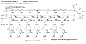
At the summing section - should be the "Cut! and "Boost! connected as well to the op-amp "Cut" and "Boost" or is it just to simulate pot?
.png")
In LTSpice, nodes with the same label are all connected together.
Some things don't look right in the plot, e.g. the 430Hz band seems to be the one with the lowest Q and it's supposed to be the highest at 1.5, the 1080Hz cut clearly has a higher Q than 0.3... Please double check...
Some things don't look right in the plot, e.g. the 430Hz band seems to be the one with the lowest Q and it's supposed to be the highest at 1.5, the 1080Hz cut clearly has a higher Q than 0.3... Please double check...
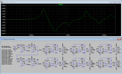
Krivium is right that even with trimmers this could be too bulky to go inside a guitar control cavity, so if your friend is positive that this is the response they want and is ok with it not being adjustable, fixed resistors are the way to go.
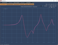
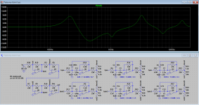
I wasn't crazy about the gain structure and, as it turns out, replacing all 2k2 resistors with 22k not only eases significantly the load on the opamps but also makes a few of the pot settings much less extreme, which in turn makes it easier to find fixed resistors that will give the right response, see attached (the gain and Q values shown are what I had to use in Neutron to match ReaEQ, you can ignore those, I put them there for convenience).
I wasn't crazy about the gain structure and, as it turns out, replacing all 2k2 resistors with 22k not only eases significantly the load on the opamps but also makes a few of the pot settings much less extreme, which in turn makes it easier to find fixed resistors that will give the right response, see attached (the gain and Q values shown are what I had to use in Neutron to match ReaEQ, you can ignore those, I put them there for convenience).
Attachments
That's what I first thought of, but those have significant interaction between adjacent bands and non-constant Q, see the paper I cited above.Gyrator circuitry: far less component sensitive than most other Opamp equalizers.
- Home
- Design & Build
- Electronic Design
- Strange EQ design