Hi,
I was asked to design an active EQ with following specs:
band 1 220hz gain +13db q=1
band 2 430hz gain -13db q=1.5
band 3 1080hz gain -4.5db q=0.3
band 4 3220hz gain +9.5db q=0.6
band 5 7070hz gain -5.5db q=0.4
band 6 15400hz gain 5db q=0.55
I find it difficult almost impossible to keep the low Q factor such as 0.3 or 0.4 since the EQ has to be active.
I was thinking about using state variable filter to get the exact result but I'm affraid that it won't work neither.
Do you have any idea what circuit topology to use?
Thank you very much
Off the top of my head, you could add / subtract in parallel (adjusting gains to get what you want) a number of bandpass filters + the flat signal, you can have the components calculated for a MFB active bandpass for the frequency and Q of your choice here: http://sim.okawa-denshi.jp/en/OPtazyuBakeisan.htm

Have you looked at mini dsp? I believe you could set all required parameters there. But its been a while last time i used it.Hi,
I was asked to design an active EQ with following specs:
band 1 220hz gain +13db q=1
band 2 430hz gain -13db q=1.5
band 3 1080hz gain -4.5db q=0.3
band 4 3220hz gain +9.5db q=0.6
band 5 7070hz gain -5.5db q=0.4
band 6 15400hz gain 5db q=0.55
I find it difficult almost impossible to keep the low Q factor such as 0.3 or 0.4 since the EQ has to be active.
I was thinking about using state variable filter to get the exact result but I'm affraid that it won't work neither.
Do you have any idea what circuit topology to use?
Thank you very much
I've found a great paper, DA Bohn - "Constant-Q Graphic Equalizers", but before getting into it, it would be good to know how the values you've been given were obtained. If this comes from an EQ plugin as I suspect, bear in mind that there are many different implementations: the response won't be the same if it's proportional Q vs. constant Q, and there are oddballs like the FabFilter Pro-Q where they have scaled the Q value so that what everyone else calls 0.707, they call 1. It would be useful to know how they got those values and even more useful if they could provide a plot with the frequency response they're after.
So he should be able to extract curves from this soft.
From there it can be defined if possible to achieve low q settings or not and how.
Constant Q eq are a way but others could be possible too imho.
The question i have is what does he try to achieve with such 'violent' settings?
From there it can be defined if possible to achieve low q settings or not and how.
Constant Q eq are a way but others could be possible too imho.
The question i have is what does he try to achieve with such 'violent' settings?
I find it hard to imagine an acoustic driver that needs that amount of EQ. could it be a cantilver style receiver connected to a small ear canal?
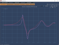
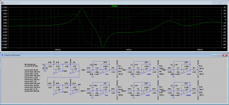
When I saw the large dB values for this set of EQ settings, I was curious as to what the frequency response function might look like. To see what's going on, I created a model in VituixCAD, which produced the following results:I was asked to design an active EQ with following specs:
band 1 220hz gain +13db q=1
band 2 430hz gain -13db q=1.5
band 3 1080hz gain -4.5db q=0.3
band 4 3220hz gain +9.5db q=0.6
band 5 7070hz gain -5.5db q=0.4
band 6 15400hz gain 5db q=0.55
As cabirio noted, it's important to know the definition of Q that was used in your EQ band specifications, so the above curve may or may not be accurate.
In any case, it would appear that the large side-by-side +13dB/-13dB EQ settings tend to significantly reduce the peak response at the frequencies in question.
The VituixCAD model that was used to generate the above transfer function is shown below.
Last edited:
Awaiting further info about the software eq used, I thought I'd give it a preliminary try, so I've put together a circuit based on Bohn's paper cited above and I've managed to get a response that looks remarkably close to what I got for the iZotope Neutron 2 eq. All the bandpass filters have been calculated here. The overall idea is shown in fig. 8 of the paper and that's what I tried first, but there was too much interaction between adjacent bands, so I went with fig. 28 where he avoids this by basically using two eq's in series, each dealing with alternate (and therefore more separate) bands. I've seen this trick before with multi-band eq's and it works beautifully here.
Attachments
Yes, R. Neve used extensively this kind of approch: low/hi ( bell/shelves) and two mid bell section in serie.
Can be found in Amek 9098 consoles. Ams/Neve constant q design ( V series eq) use same principle.
Another way would be tu use // cells as in the very first parametric eq designed ( Burgess Mcneal/ Georges Massenburg design under ITI, Sontec or GML brands). That said i'm not sure this kind of topology would accept 6 bands in // the max i've seen is 5.
Cabirio approach given in post #12 seems to be the answer imho.
That said, if you could define more accurately the guitarist setup and how ( why?) he had that outcome profile i would be interested.
I fear some di signal into a computer without cab modeller... am i on a right track here?
That said, if you could define more accurately the guitarist setup and how ( why?) he had that outcome profile i would be interested.
I fear some di signal into a computer without cab modeller... am i on a right track here?
- Home
- Design & Build
- Electronic Design
- Strange EQ design