Hi guys .... I am having a rough time with these STK0039 ICs' . I have ordered a set from China and ebay ( wasting my time and money ) with them failing from the get go.There has to be a schematic with discrete components I can build. I see there is one for the STK0050 but the circuit is a bit different than the STK0039. I love this Pioneer SX 680 AND HATE TO SCRAP IT . Can any one help ?
They are simple darlingtons and a superdiode .You can safely replace them with two darlington transistors , 4 1n4148 diodes and a few resistors.Much better compound transistor with discretes as stk chips used to fail because the drivers were sharing the final transistor temperatures.
I designed the STK-0050 replacement because of the mistrust of the knock offs plus this one can be serviced and uses 200W o/p transistors.
You can order the blank board, heatsink from the one on eBay. I show the link to the Mouser shopping cart for parts.
This was done to prevent 'HATE TO SCRAP IT"
STK-0050 replacement for SX-780 and others | Audiokarma Home Audio Stereo Discussion Forums
You can order the blank board, heatsink from the one on eBay. I show the link to the Mouser shopping cart for parts.
This was done to prevent 'HATE TO SCRAP IT"
STK-0050 replacement for SX-780 and others | Audiokarma Home Audio Stereo Discussion Forums

Hi rudedaddy
I think you first need to find out why they burn?
Even a knock off from ebay should not burn if properly installed.
Something else must be wrong?
Start by checking all voltages ...
Maybe a very old cap is gone .....
Could be many things though ...
/Baldin
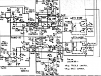
Pioneer SX-680 Service Manual (Page 18 of 41)
I think you first need to find out why they burn?
Even a knock off from ebay should not burn if properly installed.
Something else must be wrong?
Start by checking all voltages ...
Maybe a very old cap is gone .....
Could be many things though ...
/Baldin
Pioneer SX-680 Service Manual (Page 18 of 41)
Last edited:
I did check every component in the audio circuitry... but I believe discrete components are better in the long run.......
You can test the circuit without the STK installed,
temporarily solder a couple of 1K resistors from STK pins 0, to 8 and 1 to 3
temporarily solder a couple of 1K resistors from STK pins 0, to 8 and 1 to 3
You can test the circuit without the STK installed,
temporarily solder a couple of 1K resistors from STK pins 0, to 8 and 1 to 3
I agree, but he should close the feedback loop first by connecting two ~500 ohm resistors in series between pins 0 to 8 and 1 to 3, and connect the lower end of the feedback resistor (56k, post # 5) to the midpoint between the two added resistors. And disconnect everything from the amplifier input and output (speakers)!!!
Last edited:
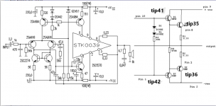
Looks pretty crude to me. Transistor choice aside (oversized and quite slow - what about e.g. BD139/140 + 2SC5200/2SA1943?), just two Si diodes + ~300 mV (~1.7 V max) is likely to be substantially underbiased for 4 B-E drops (~2.2-2.4 V or so). Any chance you could get a traditional Vbe multiplier in, or at least one more diode? Also, R4 is too big (no doubt sized for some cute TO-92L drivers that are happy at little over 2 mA). I'd say ~180R tops even for BD139/140 drivers (120R preferred), and for TIP42s I'd go as low as 75R.
You do not have to insist on getting the STK0039, the same can be replaced with STK0049, STK0059 (same housing H6-10, same pinout, quasi-complementary output) or with STK0050, STK0055 (same housing H6-10, same pinout, complementary output) or with STK0060, STK0070, STK0080 (slightly larger enclosure H8-10, same pinout, complementary output) or with ECG1280/ECG1282/NTE1282 (same enclosure H6-10, same pinout, quasi-complementary output) or with ECG1281/NTE1281 (same enclosure H6-10, same pinout, complementary output). Pin #4 is left unconnected on all modules as well as on the schematic of the Pioneer SX-680 receiver. Post a seller link here before buying because 90% of what is on offer is fake, refurbished or busted... and with some luck someone might recognize the real deal for you.
I thank you for this info .... I know that these other ICs you mention about are more expensive plus have a higher b+ voltage . This amp has a 35 volt ( +/- ) power supply . I don't know why the original ICs are failing after one or two years ( good heat sink compound used )... right now between 1 and 0 voltage is 1.48 volts ( discrete components )
That is correct, you have 1.48V across 2K= 0.74mA
Actuallly the test resistors could be as low as 220 ohm, but this a quick test that the input stage(IPS) and the voltage amp stage (VAS) are working correctly.
The mid point voltage, summing point of the two emitter resistors measured with respect to ground should be close to 0V.
Good luck
Actuallly the test resistors could be as low as 220 ohm, but this a quick test that the input stage(IPS) and the voltage amp stage (VAS) are working correctly.
The mid point voltage, summing point of the two emitter resistors measured with respect to ground should be close to 0V.
I know why, because they are crap, that is why I designed the discrete module version. I put the design out in the public domain for free, you can order your own blank pcb's or you can order the ones on eBay that come with the heatsinks to make mounting easier as the holes match the original STK-00xx.I don't know why the original ICs are failing after one or two years.
Good luck
all the STK transistor fail, including the originals, as you have them already fried... because the drivers share the same heat as the final transistors while they are idled to run lower currents than those at which the drivers would normally get that hot.
In my design, the drivers share the same heatsink as the outputs.
I think the original and knock-off STK's are just under-rated parts, but I can not be sure of that, all we see are results, which imo using them is a waste of time and $ even if they are really cheap.
I think the original and knock-off STK's are just under-rated parts, but I can not be sure of that, all we see are results, which imo using them is a waste of time and $ even if they are really cheap.
Indeed, most of the time i saw the supply rails being higher than the STK specs allowed at maximum rated power.all STK have mentioned 2 max voltages.Probably nobody cares about the second one...
Attachments
Last edited:
I don't believe anything else is wrong with the unit. On my Yamaha, an STK power amp went out 2 years from new. That took out the STK voltage amp. Real replacements were still available. Then I babied it for about 10 more years when the other channel went out, again taking the voltage amp with it. Since then, using it as a very nice preamp, but I would surely like to fix it with discrete component replacements. STK modules are garbage in my opinion. The new replacements are even worse with inferior components used. Even the originals were poor design. And why no protection circuitry with such a sensitive output amp? Unfortunately, mine are STK 1070II and STK 3070 voltage amp. I have not seen a discrete component replacement for these. Any engineers out there?
- Home
- Amplifiers
- Solid State
- STK0039 Discrete component replacement?