Hello everyone,
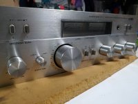
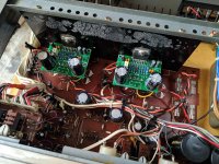
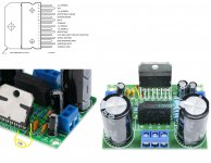
I have an AKAI amplifier that one of the channels has stopped working, one of the STK082 is shorted, I thought about replacing the STK082 but the price for the original part is too high... and I am not sure if using a non-original part is good idea... So I thought about converting the two channels to two TDA7293.
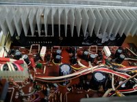
I am thinking of removing all the components that are not needed (selected zone), since they can possibly create some kind of problem...
Any recommendations?
I have an AKAI amplifier that one of the channels has stopped working, one of the STK082 is shorted, I thought about replacing the STK082 but the price for the original part is too high... and I am not sure if using a non-original part is good idea... So I thought about converting the two channels to two TDA7293.
I am thinking of removing all the components that are not needed (selected zone), since they can possibly create some kind of problem...
Any recommendations?
Attachments
Check if the voltage after the bridge / caps is compatible with the TDA.
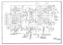
Can't read the schematic.
I did this one time on a Sony amp for a friend of mine, but as the transformer Voltage was too high I've created a center tap in one of the trafo wingdings for feeding a LM3886. Needless to say it's operating at half the Wattage say 30 or 40W, but plays fine.
Can't read the schematic.
I did this one time on a Sony amp for a friend of mine, but as the transformer Voltage was too high I've created a center tap in one of the trafo wingdings for feeding a LM3886. Needless to say it's operating at half the Wattage say 30 or 40W, but plays fine.
According to the Akai schematic the voltage after the bridge must be 36/-36.
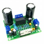
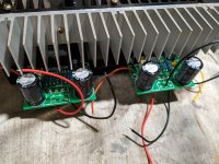
The TDA board has 50v caps, these boards also have bridge rectifiers that I will remove and connect directly to the amplifier bridge rectifier.
The TDA board has 50v caps, these boards also have bridge rectifiers that I will remove and connect directly to the amplifier bridge rectifier.
Attachments
Yes, it´s possible.
Main complication will not be "electrical" but "mechanical": available space, mounting to heatsink, etc.
Main complication will not be "electrical" but "mechanical": available space, mounting to heatsink, etc.
This schematics is weird: Look at the transistors Q113 through Q116. All of them are designated 2SC536, but each two are NPN and PNP, resp.?
Best regards!
Best regards!
the 7293 or 7294 does not need a preamp, just a potentiometer or a buffer.
I will go there without hesitation
I will go there without hesitation
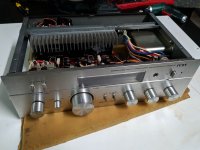
After removing the STKs, I think there will be enough space to attach the two TDA boards to the heatsink.Yes, it´s possible.
Main complication will not be "electrical" but "mechanical": available space, mounting to heatsink, etc.
I don't know, but the amp worked well for about 35 years 🙂This schematics is weird: Look at the transistors Q113 through Q116. All of them are designated 2SC536, but each two are NPN and PNP, resp.?
Best regards!
I checked some components and it seems to match the schematic.
I didn't think to remove the preamp, I would like to keep the amplifier as original as possible, maybe I'll try to reduce the gain first if it's too high...the 7293 or 7294 does not need a preamp, just a potentiometer or a buffer.
I will go there without hesitation
Attachments
Hi guys,
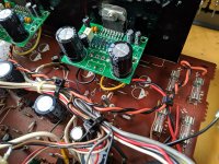
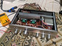
I finally got my hands on the project...
I set everything up as cleanly as possible, and the amplifier sounds pretty good, but it has a lot of background noise. It is a constant 100hz hum present even with the volume at zero, with the maximum volume it does not increase.
I thought I had a ground loop problem, initially the boards were grounded only in one spot and directly to the chassis, I removed and connected it to the pcb ground area of the STK, but with no apparent result.
Then I changed the power capacitors, but the noise remains.
Then I disconnected the input signal on the TDA boards, the noise disappeared... completely silent... I added two 2.6kr resistors in series in the inputs and it seems that the noise has attenuated a little, but it is still very audible, I need to have the volume at half to the hum won't be noticeable, which is not a good thing... I also added shielded cable to the input.
What could cause the problem? Any input / output impedance problem? is it a good idea to bypass the Q107 / Q108?
Any idea?
Thanks
Attachments
Looks like you have a classic ground loop problem ... the quick solution is to insert a 10R resistor between the signal gnd and power gnd on each TDA7293 amp module.
I thought I had a ground loop problem, initially the boards were grounded only in one spot and directly to the chassis, I removed and connected it to the pcb ground area of the STK, but with no apparent result. What could cause the problem? Any input / output impedance problem? is it a good idea to bypass the Q107 / Q108?
Please try below connection, if it can solve the ground loop problem.
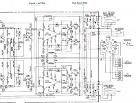
To bypass the Q107 / Q108, you disconnected both channel the white cable to the old PCB and "only solder the white wire(black wire leave disconnected)" to your TDA + input(point1), and each TAD PCB connect the output 2 and the only ground 3 to the PCB area of the STK, +V and -V as your current connection.
Attachments
Yes, there appear to be solder blobs on each speaker terminal's negative connection. The speaker terminals on the new PCB's mustn't be grounded in this application, as the speakers yet are grounded through the main board or the PSU. The only ground connection has to be either the »0« at the power supply connector or signal ground. Try which one is quieter.
Best regards!
Best regards!
Some updates:
Bypassing the Q107 and Q108 does not help much with the noise and only decreases the output power.
One thing I notice, when the amplifier is turned on, the hum is bigger and decreases after 1-2 seconds.
Bypassing the Q107 and Q108 does not help much with the noise and only decreases the output power.
One thing I notice, when the amplifier is turned on, the hum is bigger and decreases after 1-2 seconds.
Looks like you have a classic ground loop problem ... the quick solution is to insert a 10R resistor between the signal gnd and power gnd on each TDA7293 amp module.
I don't know if I understood correctly... I only have one gnd connected on each board, should I put a second ground with the input and a 10r in series?
Yes, there appear to be solder blobs on each speaker terminal's negative connection. The speaker terminals on the new PCB's mustn't be grounded in this application, as the speakers yet are grounded through the main board or the PSU. The only ground connection has to be either the »0« at the power supply connector or signal ground. Try which one is quieter.
Best regards!
Each board only has 5 wires connected, IN +; +; -; GND; SPK +
There are some spots that have solder bubbles, but they are not being used
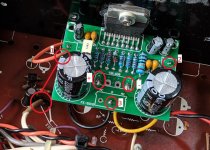
There are a few rules to follow: you must remove the two filter capacitors with a value of 2200uF 50V from the TDA7293 electronic board. You must take the positive voltage from the hole for pin 8 of the STK-082 and the negative voltage from the hole for pin 6, you must connect the ground wire DIRECTLY from pin 4 of the TDA7293 to the hole for pin 2 of the STK-082. This wire must be larger in diameter than the two power wires, or shorter. You must connect the output of the TDA7293 electronic board after the resistance R165 (left channel) and R166 (right channel). You must remove the large 10 Ohm resistor from the TDA7293 card and leave R181 C159 (for the left channel) and R182 C160 (for the right channel) in their place. In addition, the gain of the original final stage was around 21.75, that of the TDA7293 is around 33.35. When everything works it will be better to add a 10K resistor in series to the input wire of the TDA7293 electronic board.
If you have never done it, start praying!
If you have never done it, start praying!
Looks like you have a classic ground loop problem ... the quick solution is to insert a 10R resistor between the signal gnd and power gnd on each TDA7293 amp module.
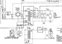
Ok, I think I realized, from the datasheet, pin 4 is gignal ground, so what you suggest is to cut the connection and put a resistance, something like this?
Attachments
You have on the non-inverting and inverting input resistors that are referenced to ground, that ground is signal (quiet) ground, the rest of ground is power (dirty) ground. You just have to put in a 10R series resistor between signal and power ground, any interference will be "consumed" on that resistor ... be sure to do it on both modules at the same time.
There are a few rules to follow: you must remove the two filter capacitors with a value of 2200uF 50V from the TDA7293 electronic board. You must take the positive voltage from the hole for pin 8 of the STK-082 and the negative voltage from the hole for pin 6, you must connect the ground wire DIRECTLY from pin 4 of the TDA7293 to the hole for pin 2 of the STK-082. This wire must be larger in diameter than the two power wires, or shorter. You must connect the output of the TDA7293 electronic board after the resistance R165 (left channel) and R166 (right channel). You must remove the large 10 Ohm resistor from the TDA7293 card and leave R181 C159 (for the left channel) and R182 C160 (for the right channel) in their place. In addition, the gain of the original final stage was around 21.75, that of the TDA7293 is around 33.35. When everything works it will be better to add a 10K resistor in series to the input wire of the TDA7293 electronic board.
If you have never done it, start praying!
I'm not an expert on amplifiers, but I like to learn 😀
Ok, let's go by parts 🙂
What is the negative effect of leaving the two 2200uF 50V filter capacitors from the TDA7293 in addition to asking for more amperage when turning on the amplifier?
Each STK had an individual line + - with fuses, once I removed the components from the STK I connected the TDA boards to each positive and negative points after the fuses.
On these boards pin 4 is connected to the power ground, the board ground is connected to pin 2 of the STK.
I removed the R181 C159 and R182 C160 🙄 but I can put it back in place.
I will remove the two large 10r resistors from the TDA, add the 10k resistor in the input signal and the 10r resistor between pin 4 and the ground, remove the filter capacitors and put R181 C159 and R182 C160 in place. If there is anything else I should do... 🙂
If there is anything else I should do... 🙂
Yes, do only one thing at a time, otherwise you will run into trouble...😉
I don't think inserting the resistor between pin 4 and the earth solves the problem, but you can try before anything else. Then do literally what I wrote in the previous message. The 2200uf capacitors short-circuit the ripple present in the general power supply on earth. But the ground they are connected to is a signal ground, not a power ground, so the noise increases!
Put the fuses back in place. I know very well the board with the TDA7293, to make your modification you have to take the ground directly from pin 4, it works better.
Every detail is important, including those that seem unnecessary.
Put the fuses back in place. I know very well the board with the TDA7293, to make your modification you have to take the ground directly from pin 4, it works better.
Every detail is important, including those that seem unnecessary.
- Home
- Amplifiers
- Solid State
- STK to TDA7293 conversion