You don't need to understand, I understand for you!  Do carefully as I wrote to you, it should be all right.
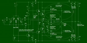
Do carefully as I wrote to you, it should be all right.You got it wrong, pin #4 and resistors located on the +/- input of TDA7293 are all referenced to the signal ground, do not separate only pin # 4 from the signal ground via 10R resistor. So, two resistors and the #4 pin are connected together to the signal ground (trace or pcb area you declare as signal ground), from where it connects to the power ground via a 10R series resistor.
As luck would have it, yesterday I was explaining similar things on the Croatian diy forum so I have a ready schematic, slightly modified with 10R resistance for your case.
As luck would have it, yesterday I was explaining similar things on the Croatian diy forum so I have a ready schematic, slightly modified with 10R resistance for your case.
Attachments
maxmix69 I did everything you said and the amp exploded 😀
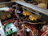
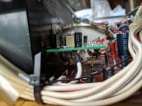
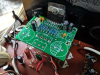
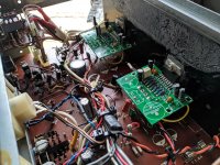
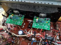
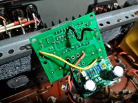
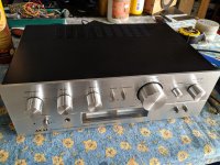
It worked, the noise was reduced to almost nothing 🙂
Thank you maxmix69 and everyone else who tried to help.
Some pictures:
It worked, the noise was reduced to almost nothing 🙂
Thank you maxmix69 and everyone else who tried to help.
Some pictures:
Attachments
-
 IMG_20200425_135726.jpg862.7 KB · Views: 127
 -
 IMG_20200425_134931.jpg852.7 KB · Views: 126
 -
 IMG_20200425_134925.jpg688.2 KB · Views: 134
 -
 IMG_20200425_134441.jpg578 KB · Views: 123
 -
 IMG_20200425_134431.jpg763.3 KB · Views: 133
 -
 IMG_20200425_134422.jpg572 KB · Views: 139
 -
 IMG_20200425_134415.jpg911.1 KB · Views: 140
 -
 IMG_20200425_030729.jpg738.3 KB · Views: 141
 -
 IMG_20200425_152018.jpg576.7 KB · Views: 129
I am happy that everything works well. This thing wouldn't have been possible without the Google translator, so thank him too!