Looks superb - great work!
What's the catch?Looks nice but wouldn't pass UL. Got a fire extinguisher? 😀
Thank you and these are what I learned from this build;
- better use good parts than cheapie ones(the current meter precision is pathetic and the potentiometer makes noise)
- be brave to try new things, you may be rewarded. 😎

I think he means it looks too safe, compared to other ones. ;-)What's the catch?
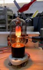
Attached is a picture of 3C24 tube in a normal operating condition.
Attachments
Can anyone explain why the load resistor values of the input differential circuit are different?
What if I use the same resistors and use balanced input?
What if I use the same resistors and use balanced input?
The 2nd plate resister controls the stage gain & operating point. Change the value,
the stage gain & operating point will shift. Might put the output stage too far off for
proper operation.. You could try small, incremental changes tho. 🙂
the stage gain & operating point will shift. Might put the output stage too far off for
proper operation.. You could try small, incremental changes tho. 🙂
Thank you jhstewart9, although I do not understand for sure.
I built 2A3 SE amp with this driver stage, using 0A2 in place of 8651 to make voltage near (-)45V.
I am glad it worked and I can adjust the 2A3 bias and the current.
I feel the gain of 8532 is a little low, compared to D3a triode strapped one.
I thought a balanced connection to the differential input stage can make more gain..?
Would the same resistor values increase the gain?
The basic circuit here is DC coupled from the input to the OPT.
Any change of conditions at the input will shift the biasing voltage on the output tube grid.
In Steve Bench's example circuit the potential at the output tube 841 grid is +9V.
That may not be optimum for other output tubes.
A sine wave test at the input & a scope tied to the amp output could be used to arrive at proper bias.
The tube gain/output voltage is shared between the differential pair plate resisters.
Any change would shift the power tube grid potential. You could try small changes
simply by paralleling something like a 1M resistor across one or the other of those plate resistors.
And note which way the output tube potential moved.
Yes, there are more than two ways to set the bias in DC-coupled circuit.
I see that the current through the differential pair plate resistors are different due to VR tube attached.
I see that the current through the differential pair plate resistors are different due to VR tube attached.
- Home
- Amplifiers
- Tubes / Valves
- Steve Bench A2 amplifier: what's that coupling stage?