Can anyone explain how the coupling with the voltage reference tube // 5.6nF cap works? The designer states that it is a fully DC coupled amp, but I can't get my head around how the signal passes in that middle stage if it weren't through the cap. His explication leaves me equally perplexed:
"Incidentally, notice that the voltage at the grid of the cathode follower driving the 841 is near zero volts. One could then ask why the complication of adding the DC coupling, and the reference tube. Well, indeed I tried that, and the amp measured OK, but sounded VASTLY inferior to the DC coupled circuit. Distortion cancellation anyone?"
http://diyaudioprojects.com/mirror/members.aol.com/sbench/a2part2.html
Thanks for shedding a light,
Simon
The differential resistance - that is dv/di not v/i - of a gas regulator tube is on the order of 200 ... 300 ohm, while the imedance of the bypass cap depends on frequency z=1/(2*pi*f*c) and at 5.6nF stays above 200 ohm for anything below 150kHz or so. Which means that audio signals pass mainly through the tube rather than through the cap. The cap is there to suppress noise from the gas regulator.

That's a very clear explanation. Cheers, Sorento!The differential resistance - that is dv/di not v/i - of a gas regulator tube is on the order of 200 ... 300 ohm, while the imedance of the bypass cap depends on frequency z=1/(2*pi*f*c) and at 5.6nF stays above 200 ohm for anything below 150kHz or so. Which means that audio signals pass mainly through the tube rather than through the cap. The cap is there to suppress noise from the gas regulator.
Hi, I just built this amplifier without the 5.6nF capacitor across the regulator tube and it works just fine.
In fact, more than fine and it sounds wonderful.
In fact, more than fine and it sounds wonderful.
Thanks for your feedback! I still plan to build it too (found the output tubes on discount), but with the 48v Cisco smps to save $$ and avoid complexity. I saw you used those as well in another amp. What kind of power supply are you using for this build?Hi, I just built this amplifier without the 5.6nF capacitor across the regulator tube and it works just fine.
In fact, more than fine and it sounds wonderful.
Hi Klimon, I am pretty fascinated by the ease of 48V Cisco power supply.
As in the circuit, I use similar power voltages. -96V, +144V, +288V, and 480V since the output tube is 808.
As in the circuit, I use similar power voltages. -96V, +144V, +288V, and 480V since the output tube is 808.
DC coupling using a specially selected NE2 was common in the daze of the vacuum tube Op Amp. For example, in Philbrick products.Can anyone explain how the coupling with the voltage reference tube // 5.6nF cap works? The designer states that it is a fully DC coupled amp, but I can't get my head around how the signal passes in that middle stage if it weren't through the cap. His explication leaves me equally perplexed:
"Incidentally, notice that the voltage at the grid of the cathode follower driving the 841 is near zero volts. One could then ask why the complication of adding the DC coupling, and the reference tube. Well, indeed I tried that, and the amp measured OK, but sounded VASTLY inferior to the DC coupled circuit. Distortion cancellation anyone?"
http://diyaudioprojects.com/mirror/members.aol.com/sbench/a2part2.html
Thanks for shedding a light,
Simon
Anyone building DC coupled amps would be familiar with them. I used ordinary NE2's or NE51's for level shifting in the error amp of
regulated power supplies. An earlier device used is the 991 Neon Bulb. In circuit these were often in parallel with a small cap,
never more than 0.1 microF. 🙂
Steve Bench did a lot of good work looking at circuits that really were 'outside the box'.👍
Attachments
Great to hear that it works with those, Chul. And what luck that all voltages in the circuit are so close to a multiple of 48.Hi Klimon, I am pretty fascinated by the ease of 48V Cisco power supply.
As in the circuit, I use similar power voltages. -96V, +144V, +288V, and 480V since the output tube is 808.
808 is the best looking tube ever imo.
If you have pictures of the amp, I'ld love to see it ;-)
Cheers,
Simon
It was made for a test just two days ago and I need to build it again in a better-looking case.Great to hear that it works with those, Chul. And what luck that all voltages in the circuit are so close to a multiple of 48.
808 is the best looking tube ever imo.
If you have pictures of the amp, I'ld love to see it ;-)
Cheers,
Simon
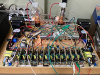
Built on a chopping board, it looks ugly like this.
Sorry, but you asked for it. 🙂
Attachments
The usual story is that gas tubes HISS real bad. 5nFd is about right to pass all audio around the gas tube.I just built this amplifier without the 5.6nF capacitor across the regulator tube and it works just fine.
However I can also believe that, for high-level work like power tube grid, the hiss may be unimportant.
(BTW: too large a cap may set up an oscillator. )
Hi, my speaker is on the sensitive side (96dB), and I think I heard some static noise near the speaker. Maybe I need to check with and without 5.6nF. Thank you.The usual story is that gas tubes HISS real bad. 5nFd is about right to pass all audio around the gas tube.
However I can also believe that, for high-level work like power tube grid, the hiss may be unimportant.
(BTW: too large a cap may set up an oscillator. )
p.s.It was made for a test just two days ago and I need to build it again in a better-looking case.
Built on a chopping board, it looks ugly like this.
Sorry, but you asked for it. 🙂
Are you sure, that -below- 80mA is "enough" in this (below +30V grid voltage?) operating point?
These type of tubes requiring the "crimson plate" to activate getter properly.
The output transformer is for max. 80mA to the primary and I only keep the current.p.s.
Are you sure, that -below- 80mA is "enough" in this (below +30V grid voltage?) operating point?
These type of tubes requiring the "crimson plate" to activate getter properly.
As of now, it is adjusted at 480V 80mA. Of course I am not sure of this.
Typical circuits from Japan shows about 350V 120mA but I do not have the transformer for this.
Do you have other suggestions? The other transformer that I have is for 90mA max.
I also will try para-feed method.
If you read 808 datasheet, this operating point not quite optimal for this tube, the current is low.
https://www.google.hu/url?sa=t&rct=...49/8/808.pdf&usg=AOvVaw0qbDdpHYf64NuEMExki5lE
secondly: even with this low positive grid voltage the grid current is significant. Are you sure, that driver capable even 20mA continuos output current?
https://www.google.hu/url?sa=t&rct=...49/8/808.pdf&usg=AOvVaw0qbDdpHYf64NuEMExki5lE
secondly: even with this low positive grid voltage the grid current is significant. Are you sure, that driver capable even 20mA continuos output current?
Hi Euro21,
First, this prototype build is not final, and like I said the available output transformer only allows max 80mA.
808 is 50W plate dissipation tube and I hope to try 480V and 100mA with para feed structure.
As of now, it is not the best but I can enjoy the sound of each step along with the change.
Maybe I have to listen to this as of now until whatever parts are available. This way I can see the change of sound clearly.
Another variable is that I am using Shade feedback or partial feedback.
I see that you looked into the picture closely. Maybe you noticed that I am using each half of two 6H30 tubes instead of one.
This is due to the heater supply of 12V, and I can parallel the two sections to increase the current capability.
And there's no hurry here. My friend is bringing 811 and 812 tubes to put into this circuit, and we will enjoy whatever difference they bring. 🙂. Nothing is tuned best, I am using whatever that I have instead of using the so-called good parts like the Tango transformer, etc.
Cheers
Quite the contrary : very nice! Don't hesitate to share your further experiments here.it looks ugly like this
As I check the 6H30 datasheet it has no problem with 20mA. Thank you for reminding this.secondly: even with this low positive grid voltage the grid current is significant. Are you sure, that driver capable even 20mA continuos output current?
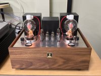
I finished 808 SE in a wood base. I really like this amp.
It is Steve Bench's 841 amp driver section into RCA 808 with 384V on the plate and 110mA.
Big and heavy 200mA plate choke + 10uF 800V para feed cap + 20:1 turn ratio para feed OPT.
I used changeable partial feedback of 2uF+10~60K ohm. But I do not feel a big difference. (I have dumb ears and it takes me many days to feel the subtle difference.)
Very cool driver stage and I am going to apply this to my 2A3 SE amp. 🙂
Attachments
- Home
- Amplifiers
- Tubes / Valves
- Steve Bench A2 amplifier: what's that coupling stage?