Is there a reason why people feel there is even a need for a standby switch on this design?
Just asking.
Glenn
On my first build, I did not have a standby switch and I was using a 5u4gb rectifier which ramps up voltage very quickly, the tubes are not conducting yet but the rectifier is giving full voltage already (like an SS rectifier).
I was using 450V capacitors on the PSU and after a couple of months, one exploded while I was tweaking the amp at around 3:00 am... 😱
I live in a village with full security, so it was quite embarassing to explain to the security guards that came into my door what happened!
So I did install a standby switch which is a double position, double pole (one pole for the CT of the HT and one for one leg of the 5V that goes to the heater of the 5u4gb). I just need about 30 seconds and then I flip the standby switch. The 5V switching that I did was to remove the thump when only the CT of the HT is switched.
I once referred to the tube type relay used on my Oddblocks project. It is pretty neat and adds some aesthetic value to the amp IMHO. Check it out at the diyaudioprojects.com site, look at the Oddblocks project by Bruce Heran. The tube type relay sells for about $6 at AES and gives a 30sec delay. It mught be a viable alternative to a switch, fully automated.
Jeff
Jeff
I once referred to the tube type relay used on my Oddblocks project. It is pretty neat and adds some aesthetic value to the amp IMHO. Check it out at the diyaudioprojects.com site, look at the Oddblocks project by Bruce Heran. The tube type relay sells for about $6 at AES and gives a 30sec delay. It mught be a viable alternative to a switch, fully automated.
Jeff
That should be an excellent solution (are those devices called amperites?), much better than a standby switch or the SS device that I use. I have a Kiwi friend who gave me a 1 minute delay circuit with a couple of transistors and capacitors. It needs 12VDC and will control a relay.
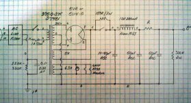
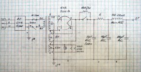
Thanks again everyone, I've redrawn the schematic...
-What do you guys think of the modified PSU schematic?...
-What do you guys think about the 150K/3W resistor in parallel to the SPST switch after the rectifier and between C1 according to the valvewizzard1 article?... This will be the easiest to implement to my existing construction.
-Won't there be any DC arcing every time I flick on the switch in this position?... If yes, I may use the DPDT switch (according to scitizen17) after the 375V secondaries just before the rectifier and call it a day!
-Is the bleeder resistor in the right position?
I am planning on 3 separate star grounds to chassis: 1) For PSU. 2) For Amp. 3) Input jacks and potentiometer.
Jeff, I already bought those (2) Amperite 6NO30 relay tubes back when talking about the Oddblock Amp. I could use them with, but I'd really like to keep this first newbie project very simple. Since I already drilled the wooden case, I am stuck having to use a standby switch. I am about to add 6 more parts and quickly this PSU is getting very complicated very fast.
This morning, I ordered a NOS NIB JAN Philips 5U4GB for $17 total cost to practice on. If all goes well, I'll invest in a NOS coke bottle type rectifier. I hope I don't blow out the Genalex Gold Lions too. But, I am going to check my wiring for a solid week before I fire it up... No pun intented. 🙂
Attachments

I am unfamiliar with the addition of this 150K/3W resistor that bypasses the switch. What is it's function?
Jeff
Jeff
I am unfamiliar with the addition of this 150K/3W resistor that bypasses the switch. What is it's function?
Jeff
I'd like to know too.
I've used a snubber capacitor with a resistor across switches, but never just a resistor.
An externally hosted image should be here but it was not working when we last tested it.
alexg said:I was using 450V capacitors on the PSU and after a couple of months, one exploded while I was tweaking the amp at around 3:00 am...
So the real issue was that the B+ exceeded the capacitors ratings. So if I have ASC motor run caps I shouldn't need the standby switch, right?
Glenn
Last edited:
who can tell me
what is the differents in power output between el34 in triode and kt88 in triode?
greetings ko
what is the differents in power output between el34 in triode and kt88 in triode?
greetings ko
Jeff wrote:
According to the article suggested by scitizen17 (http://www.freewebs.com/valvewizard1/standby.html), the resistor in parallel to the switch is designed to serve as a "soft start" standby switch to extend the life of the rectifier. If the anode current increases gradually while the heaters warm up, then the inrush surge and cathode poisoning can be prevented. Another benefit is that the capacitors are allowed to partially charge up during standby, and there should be little delay when the amp is turned on.
To avoid excessive heat on the resistor, limit the dissipation to 1W. The initial current will be
P=V^2/R
R=(V^2)/P
R=(400^2)/1 = 160,000 or ~150k ohm
Jeff, an additional CR before the C1 reservoir capacitor seems like a great idea. I didn't even get to determine the actual value for R since the rectifier blew. This way I'll protect the rectifier with a 10uF and bring down the voltage to 400V with an R, and decrease ripple. I'll have to mount the capacitor internally, I hope there is room - if I can't fit an ASC, then I may try a Solen 10uF/630V. The 10uF C1 will also give me more choices with different rectifier tubes, especially with one's which have lower maximum filter capacitor values.
Thanks again, guys!
I am unfamiliar with the addition of this 150K/3W resistor that bypasses the switch. What is it's function?
According to the article suggested by scitizen17 (http://www.freewebs.com/valvewizard1/standby.html), the resistor in parallel to the switch is designed to serve as a "soft start" standby switch to extend the life of the rectifier. If the anode current increases gradually while the heaters warm up, then the inrush surge and cathode poisoning can be prevented. Another benefit is that the capacitors are allowed to partially charge up during standby, and there should be little delay when the amp is turned on.
To avoid excessive heat on the resistor, limit the dissipation to 1W. The initial current will be
P=V^2/R
R=(V^2)/P
R=(400^2)/1 = 160,000 or ~150k ohm
Jeff, an additional CR before the C1 reservoir capacitor seems like a great idea. I didn't even get to determine the actual value for R since the rectifier blew. This way I'll protect the rectifier with a 10uF and bring down the voltage to 400V with an R, and decrease ripple. I'll have to mount the capacitor internally, I hope there is room - if I can't fit an ASC, then I may try a Solen 10uF/630V. The 10uF C1 will also give me more choices with different rectifier tubes, especially with one's which have lower maximum filter capacitor values.
Thanks again, guys!
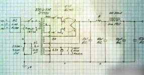
Here are 2 viable schematics for the PSU from my cell phone camera.
-I am going to try the circuit with/without the RC line ground to chassis ground.
-Try different values of R in the CR filter: 20, 50, 100, etc. to get the desired 400V B+.
-Try the DPDT or DPST after 375VAC secondary.
-Try the 150K/3W R parallel to SPST after rectifier.
Try with/without 300k bleeder resistor.
Attachments
Help finding website again
Somebody here I believe referred me to a website once that allowed you to download a freeware signal generator program. I can't remember the site and was hoping to get the link again.
Thanks,
Jeff
Somebody here I believe referred me to a website once that allowed you to download a freeware signal generator program. I can't remember the site and was hoping to get the link again.
Thanks,
Jeff
Jeff wrote:
Jeff, an additional CR before the C1 reservoir capacitor seems like a great idea. I didn't even get to determine the actual value for R since the rectifier blew. This way I'll protect the rectifier with a 10uF and bring down the voltage to 400V with an R, and decrease ripple. I'll have to mount the capacitor internally, I hope there is room - if I can't fit an ASC, then I may try a Solen 10uF/630V. The 10uF C1 will also give me more choices with different rectifier tubes, especially with one's which have lower maximum filter capacitor values.
Thanks again, guys!
I used a Solen, it worked perfectly!
Jeff
Visual Analyzer
scope, spectrum analyzer, waveform generator, etc.
Link: Introduction
scope, spectrum analyzer, waveform generator, etc.
Link: Introduction
Somebody here I believe referred me to a website once that allowed you to download a freeware signal generator program. I can't remember the site and was hoping to get the link again.
Thanks,
Jeff
Here are 2 viable schematics for the PSU
.
I do not like the way you connect AC ground to chassis.
The protective earth should be connected directly to chassis for safety.
This connection should be close to the AC connector, and need not (should not?) be the same as the signal ground point.
I will rather suggest to connect the signal ground semi-floating. Either with RC, or a couple of diodes in parallel with a cap.
The bleeder is a good idea.
For a simple tone generator and other small useful software look at our member Svente's site: TMH KTH :: Music software by Svante Granqvist
Svein_B
Last edited:
Svein, I am planning on 3 separate star grounds to chassis:
- For PSU.
- For Amp.
- Input jacks and potentiometer.
Should I connect the IEC Line filter ground wire directly to the chassis as its own "star ground," separate from other star ground connections in the PSU?
- For PSU.
- For Amp.
- Input jacks and potentiometer.
Should I connect the IEC Line filter ground wire directly to the chassis as its own "star ground," separate from other star ground connections in the PSU?
Svein, I am planning on 3 separate star grounds to chassis:
- For PSU.
- For Amp.
- Input jacks and potentiometer.
Should I connect the IEC Line filter ground wire directly to the chassis as its own "star ground," separate from other star ground connections in the PSU?
I generally connect the earth ground (green) to the chassis and connect it to the power supply ground closest to the CT connection to the ground with a X2 type 0.22-0.33uF cap in parallel with a 1-2 watt 100K to 330K resistor. I learned this from Bruce Heran (Oddblock creator), he gave his reason for doing this once, I don't honestly remember why. That was back in the day when I just did what I was told and didn't ask as many questions😛
Jeff
Sorry, should clarify...the parallel cap and resistor is the only connection between the power supply ground and the chassis. The earth connects to chassis, the chassis connects to powersupply through the X2 capa and resistor in parallel. I don't think I would connect the power supply ground directly to the chassis.
Jeff
Jeff
Star Ground
Just a comment,
I believe you should have only one ground point for all grounds in the system. Sure you can have different star points, but only one point should connect to the chassis.
Also I agree with Svein, the IEC ground should connect directly to the chassis close to the socket location.
Svein, I am planning on 3 separate star grounds to chassis:
- For PSU.
- For Amp.
- Input jacks and potentiometer.
Should I connect the IEC Line filter ground wire directly to the chassis as its own "star ground," separate from other star ground connections in the PSU?
Just a comment,
I believe you should have only one ground point for all grounds in the system. Sure you can have different star points, but only one point should connect to the chassis.
Also I agree with Svein, the IEC ground should connect directly to the chassis close to the socket location.
Last edited:
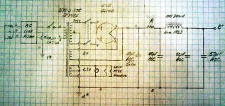
I've redrawn the schematic with separate ground for the IEC plug/Line filter and PSU star ground.
Scitizen17 wrote:
Should I go with a 12ga. ground buss wire connecting all the grounds from the PSU, amp, and inputs and have it terminate to one point on the chassis?
Which would be better for low hum and noise: Several star grounds to chassis or a buss wire connecting all grounds and terminating to one chassis grounds. I've seen it both ways on other circuits.
Scitizen17 wrote:
I believe you should have only one ground point for all grounds in the system. Sure you can have different star points, but only one point should connect to the chassis.
Should I go with a 12ga. ground buss wire connecting all the grounds from the PSU, amp, and inputs and have it terminate to one point on the chassis?
Which would be better for low hum and noise: Several star grounds to chassis or a buss wire connecting all grounds and terminating to one chassis grounds. I've seen it both ways on other circuits.
Attachments
I've redrawn the schematic with separate ground for the IEC plug/Line filter and PSU star ground.
Scitizen17 wrote:
Should I go with a 12ga. ground buss wire connecting all the grounds from the PSU, amp, and inputs and have it terminate to one point on the chassis?
Which would be better for low hum and noise: Several star grounds to chassis or a buss wire connecting all grounds and terminating to one chassis grounds. I've seen it both ways on other circuits.
I believe the article (linked below) has been referenced before by porkchop61 before, I may be wrong.
Star Grounding
I used one (1) ground point to the chassis for all circuit grounds. I used 18AWG wire. I grounded the IEC socket to the chassis close to the socket. I have no hum or noise. A photo of my grounding (green wires) can be seen at post #292. I have no experience using the RC circuit so I have no input with regards to that method.
I chose to use a 5U4GB exclusively, so I took the HT from the 5V center-tap.
Last edited:
Thanks, everyone for sharing your knowledge and experience on this project. A newbie can only learn so much from just looking at a schematic...
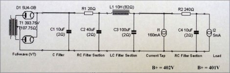
Here is the PSUD2 simulation with the addition of CR filter ahead of the 40uF as a preventive measure for the rectifier tube. The values I used are Solen 10uF/630V + 20ohm/20W to give me 402V @ the 160mA tap and 401V @ the 5mA tap.
Having read your great responses, I have just one final question about implementing filament transformers... Is it correct to assume that there are 2 ways to supply the heater voltage for this project?...
1. By using the 5VAC leads and ignoring the CT.
2. By using the CT and one of the 5VAC leads, and ignoring the other 5VAC lead.
Thanks!
Attachments
- Status
- Not open for further replies.
- Home
- Amplifiers
- Tubes / Valves
- stereo SE kt88 build ... abdellah diyaudioprojects design