I did try a tapped horn, didn't work out too well. I'm not sure what to call the design I ended up doing.
It's technically a 6th order BP due to both the driver and rear vent being recessed enough for the 'trapped' air to exert a small amount of acoustic loading on the front of the driver and due to its long, tapered rear vent, this makes it a TH, just a very low gain one.
GM
The back loaded horn will require a hipass regardless of the 50v input (no sealed rear chamber for excursion control below Fc), A lot of its smoothness in passband also relies on the smoothing of response when adding more horns to the stack (a phenomenon which IM *pretty* sure only occurs with FLHs, although as modeled with hornresp is attributed to all designs), AND the added smoothness from corner loading.
I was reluctant to rely on corner loading to have a smooth response. Although, I figured that I had my old 18's in the corner for almost 2 years, I'll just do the same with these.
hell, givin the 50v drive input into the SI, even our little friend the LAB 12 can almost match output down to 30hz in that sized package (FLH) without exceeding xmax (this isnt a shot abcdmku, just a observation).
For the same price (after shipping) I rather have the SI 😉
As far as the fold goes... I dunno. I'm absolute rubbish at it (learning still). Your cad work is actually quite inspirational, you art degree paid off 😀
Thanks! and I still got 2 more years of college, I'm only 19 😛 I'm tempted to try and fold that into the box!
It's technically a 6th order BP due to both the driver and rear vent being recessed enough for the 'trapped' air to exert a small amount of acoustic loading on the front of the driver and due to its long, tapered rear vent, this makes it a TH, just a very low gain one.
I did add in the 3" recess in the Transmission Line software, the change was negligible. It wasn't worth changing the Hornresp input. Interesting how it can be technically considered a BP! I used that logic to consider it a TH, but I think Shadydave is right saying its more of a back loaded horn.
sine143- In reply to the power ratings here are my findings:
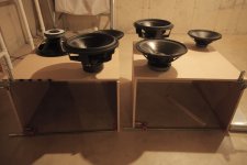
The first picture is the MCM. It's about 9 wires thick for the width of the screw driver. The screw driver is 3mm thick. This makes the wire diameter about 0.33mm. The SI (second picture) is 4.5 wires thick or 0.66mm. This means that the MCM driver uses 28AWG (0.321mm) wire and the SI uses 22AWG (0.644mm). Does that sound right? I'm not 100% sure how to determine power ratings form this though.
(The image quality, for the SI isn't, that great since I had to zoom into the pixels. The voice coil is hard to see and doing macro wasn't an option because I didn't want my camera that close to the magnet)


Here's video of the SI's being broken in at 15Hz, the strobe is 16Hz (thats why theres so much flicker, the video is at 30fps)
https://www.youtube.com/watch?v=GabKuCIzEe0
And my current progress:
https://www.youtube.com/watch?v=GabKuCIzEe0
And my current progress:
Attachments
Wire thickness doesnt have as much to do with voice coil power handling as you might think. First off, Hitting a 4 ohm driver with 50 volts is like hitting an 8 ohm driver with about 75 volts from a heat standpoint. There are plenty of other factors that contribute to voice coil tempterature as well (surface area due to VC diameter is one of the most popular cited examples). Gap width, and the overall cooling design are also important factors, which likely vary highly between the MCM and the SI
that being said, 50v will be no issue. I was only concerned with power handling if driven to xmax (with about 90 to 100 volts) for sustained sine material. It looks like ricci ran sweeps with it around 118v so thats promising to say the least.
Ya vid is private!!!
that being said, 50v will be no issue. I was only concerned with power handling if driven to xmax (with about 90 to 100 volts) for sustained sine material. It looks like ricci ran sweeps with it around 118v so thats promising to say the least.
Ya vid is private!!!
The SI seems to have very good venting. The gap I took the picture through is to vent the VC and it pushes a lot of air in and out of there.
"It looks like ricci ran sweeps with it around 118v so thats promising to say the least."
Where did you find this?
Try the video again, I changed it as "unlisted".
"It looks like ricci ran sweeps with it around 118v so thats promising to say the least."
Where did you find this?
Try the video again, I changed it as "unlisted".
Note* this only means it will survive 118v peaks for short periods (24 second sweep). Its VERY unlikely it could survive this output level for any greater length of time, even minutes.
I wouldnt push it past 80 volts sustained.... I likely wouldnt even go past 60 volts sustained sine. Esp since once this closeout sale is over they are likely gone
Josh Ricci wrote:so it should take 80-100v no problem?
"Indeed Stereo Integrity confirms that the power rating for this driver is based on the mechanical overload not what the coil will handle thermally. They recommend 600w and no more for this driver. The very compliant suspension results in little power being needed to move the driver to full stroke. SI's recommendations for this woofer make sense in light of this and the driver will not make much use of more than 5 or 600w of power without getting into trouble. Depending upon the particular enclosure design more power could possibly be used but careful measurement and simulation would be needed to assess the wisdom of applying more power."
49 volts into a nominal 4 ohm load is about 600 watts.
the big debate here is due to the first sentance
"Indeed Stereo Integrity confirms that the power rating for this driver is based on the mechanical overload not what the coil will handle thermally."
I think its clear they did not intend the SI 18 to be used in a horn for 30hz up (thus controlling excursion admirably in passband vs sealed or vented)... so what is the real, thermal RMS limit of the coil (givin that either OPs or my design can control excursion up to 90v).
I think the best explanation to OP is this. The 180 dollar, Chinese made SI 18, 4 ohm, with its 2.5 inch coil DEFINITELY cannot handle as much RMS power (from a thermal standpoint) as the 500 dollar, italian made BC 18sw115 with its 4.5 inch voice coil. Which art can supply for us as I cant find the AES rating for the 4 ohm model 😛
Last edited:
Hi sine142,the big debate here is due to the first sentance
Who cares about RMS or Xmax when there is no sufficient motor force to control it?
Hi sine142,
Who cares about RMS or Xmax when there is no sufficient motor force to control it?
I don't know, but that video made me horny.
And I know I'm not the only one

With a BL of 21 its got quite a bit of motor, BL/Sqrt(Re) of around 11.4. I just picked another random 18 thats been getting some chat the new dayton "BC/RCF knockoff" that has a bl/sqrt(RE) of 10.24. Granted the SI is boasting 2x as much xmax, but again, I'm the one trying to say stick to no more than 60v, at which point the FLH stays below 15mm excursion with a 25hz hipass.
Hi sine143,
Check the Q parameters and calculate the EPB. It explains why Josh tested it in a closed box for his power tests.
Quote from Data-bass:
“The woofer specs lend it to use in large EBS vented or even IB installs but mechanical power handling in large enclosures should be kept in check with the highly compliant suspension as it can be bottomed.”
qts .38...
My horn design has a 50 liter rear chamber. Thats pretty damn small for an 18 (due to highly compliant suspension).
My horn design has a 50 liter rear chamber. Thats pretty damn small for an 18 (due to highly compliant suspension).
Hi sine143,qts .38... My horn design has a 50 liter rear chamber. Thats pretty damn small for an 18 (due to highly compliant suspension).
I apreciate your explanation but you might take a look at the Effective Bandwidth Product:
EBP = Fs/Qes
I know... its very low (48), but for 30hz horns its been shown that low EBP can be used effectivly (lab 12, EBP of 56) with the addition of a small rear chamber, granted with a much lower mms and xmax So I can see your concern
IMO its the wrong tool for a 30hz and up enclosure for music playback, but the OP, as well as many others have chosen/purchased it, so I did what I could to make a reasonable enclosure imo.
sorry if I came off like a prick lol.
IMO its the wrong tool for a 30hz and up enclosure for music playback, but the OP, as well as many others have chosen/purchased it, so I did what I could to make a reasonable enclosure imo.
sorry if I came off like a prick lol.
- Status
- Not open for further replies.
- Home
- Loudspeakers
- Subwoofers
- Stereo Integrity 18" HT-18D2