Hi Ho Again... !
I am right now working on a PFC preregulator for my new subs.
I still love these simple boost converters as described in this application note: http://www.st.com/stonline/books/ascii/docs/10238.htm
But my design is enhanced to an wide range input voltage (120V-274V). Furtheron in my application the load will vary between
30W (just turned on, but very low volume) and full power of about 500W.
Sounds good, but calculates bad.
The lowest operating frequency (120V / 500W) should not come down into the audioable frequency range. Say not below 25kHz.
OK. This means the PFC inductor must be at least 350µH.
During line peak this will result in about 26kHz, while ramping up to 40kHz during line zero crossing. Fine.
But if the circuit is running at low power (30W) and an AC line of
274V is applied, then the frequency will exceed 1MHz during line peak.
No chance for me to handle this.
So I am experimenting with a stepped gap choke, that will result in a high inductance for low currents and lower (but stable) inductance at high current levels.
Attachments
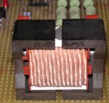
I am planning to use two EVD36 ferrite chokes in series.
The main winding is 41 turns in 3 layers. Wire is a 150x0.1mm stranded HF-litz with additional silk covering.
The auxiliary winding is a teflon isolated AWG 30, 12 turns.
(Probably 6 turns will do it, but the auxiliary is a side topic ....)
Each choke has a 2.8mm gap in each leg. I am partially closing these gaps with ferrite as shown in the pic above.
The small ferrite short cuts have an area of 20mm^2 in each outer leg and and 40mm^2 in the center leg, while the entire EVD36 offers an Ae=150mm^2.
For low currents the short cuts provide a low magnetic resistance and the inductance is high. At high currents these short cuts run into saturation and the choke show an inductance as a normal gapped design. For the short cuts I have to use a low loss ferrite as N87 or similar, to keep hot spots during saturation acceptable.
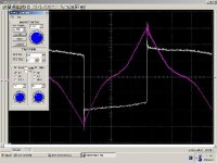
I measured a single choke and got an inductance around 600µH at low levels and linear 160µH in the range between 5A - 15A.
See attached screen shot.
White Trace = voltage across choke: 100V / Div.
Red Trace = current though choke: 5A / Div.
PS.
Destroyer X : Thanks for correcting the phase shift of my face *rofl*
Eva: I was not able to get the MPP cores, so I could not try if they
would work with respect to the losses. I did not try normal iron powder because their losses would be 5 times higher....
The main winding is 41 turns in 3 layers. Wire is a 150x0.1mm stranded HF-litz with additional silk covering.
The auxiliary winding is a teflon isolated AWG 30, 12 turns.
(Probably 6 turns will do it, but the auxiliary is a side topic ....)
Each choke has a 2.8mm gap in each leg. I am partially closing these gaps with ferrite as shown in the pic above.
The small ferrite short cuts have an area of 20mm^2 in each outer leg and and 40mm^2 in the center leg, while the entire EVD36 offers an Ae=150mm^2.
For low currents the short cuts provide a low magnetic resistance and the inductance is high. At high currents these short cuts run into saturation and the choke show an inductance as a normal gapped design. For the short cuts I have to use a low loss ferrite as N87 or similar, to keep hot spots during saturation acceptable.
I measured a single choke and got an inductance around 600µH at low levels and linear 160µH in the range between 5A - 15A.
See attached screen shot.
White Trace = voltage across choke: 100V / Div.
Red Trace = current though choke: 5A / Div.
PS.
Destroyer X : Thanks for correcting the phase shift of my face *rofl*
Eva: I was not able to get the MPP cores, so I could not try if they
would work with respect to the losses. I did not try normal iron powder because their losses would be 5 times higher....
Attachments
.....uhps, sorry!
Did I say "....in the application note ..." ?
Well, I meant the schematics (fig 23 & 24) in the data sheet.
The application note with the Fixed Off Time (FOT) control
should solve my frequency range issue. But I am still sticking
to the critical conduction mode (CCM). My reason for this simple.
EMI. In the lower frequency range the CCM generates more EMI, but
in this range it is easy to filter and also the radiated energy is not
so critical.
The advantage of CCM is the perfect softswitching, which reduces the EMI in the frequency range above 10MHz..... up to 1GHz.
And this frequency range is the most sensitive for radio and TV.
I simply do not feel comfortable in audio equipment with such noise generators. Hard to measure, hard to filter. So I prefer to generate less, than trying to filter & hope for miracles of screened enclosures....
Hm, Eva's snubber (http://www.diyaudio.com/forums/showthread.php?s=&threadid=54440&perpage=10&highlight=&pagenumber=2) combined with the FOT approach could be another option....
Anyway. Looking forward to your comments experiences !
I don't know how this particular topology will behave, but I have experimented with flybacks working in crytical conduction mode, and in practice, the minimum-load switching frequency is gently limited by the switching times, crossover times and the dead time. Note that crossover times increase dramatically at low currents due to the internal capacitance of the diodes and the switches.
I've also experimented with the stepped gap approach to create non-linear inductors and it works fine, but be aware that these small ferrite pieces will show some losses.
However, I think your switching frequency in practice will not increase above 400Khz, even using a standard inductor and very small loads.
Good to hear that you got good results with this approach.
I guess you are right that my max. switching frequency may not come as high as I calculated first.
My calculation takes into consideration 500ns between demag of the choke and turning ON the switch.
The lower power PFCs (approx. 100W) which I am used to, typically show a resonant sloping down of Uds with such values. With proper adjustment, MOSFET turn ON can hit into the minimum of this sloping .
But I have no idea about the times, which I will get with these higher power devices. Probably the increased capacitances will slow down the system. On the other hand the inductance is also less....
May be 800ns ? 😕
Hm, also I neglected the switching time to turn OFF the FET. I guess I should adjust it to approx. 200ns. This should be a reasonable trade off between switching losses and EMI/RFI.
Up to now, I did not examine the crossover times of the diode.
I guess you mean the time between current zero in the diode and
beginning of the down sloping Uds ? Hm, up to now, I simply had looked at this as a part of my down sloping time....
With these new values I am still getting 780kHz at 30W/274V.
And when I am considering about initial 2x600µH of a stepped gap design, then it caculates to 510kHz.
Wow. I would have expected more influence of the increased inductance! 😱
The driving losses still calculate to more than 0.7W in this condition
and I want to drive the Fet directly from the PFC-chip, without
additional driver... hm, even if I guess that half of the driving losses will settle in the gate drive resistor. Less would be nice.
Seems like I should try to trim the choke to even higher
L values at low currents.
Due to resonances and non-linear semiconductor capacitances, I think that the low-load switching frequency is almost unpredictable, or at least it's much harder to predict than to build a prototype of the actual circuit and measure it. I recommend you the latter 🙂
I guess the frequency will be lower than expected.
I guess the frequency will be lower than expected.
You are right.
...I am on the way, - in small baby steps... 😉
No chance for me to compete with your DIY activity & speed !
Luckily I was able to start using both new sub cubes
with my old electronics. It's little bit a combination, but even without perfect Linkwitz Transform (...my old sub was only using double integration below fs for equalizing)
they are doing an impressive job...
...must leave now. Sunny weather and "BUGA 05" in Munich is calling.

...I am on the way, - in small baby steps... 😉
No chance for me to compete with your DIY activity & speed !
Luckily I was able to start using both new sub cubes
with my old electronics. It's little bit a
combination, but even without perfect Linkwitz Transform (...my old sub was only using double integration below fs for equalizing)they are doing an impressive job...
...must leave now. Sunny weather and "BUGA 05" in Munich is calling.
- Status
- Not open for further replies.
- Home
- Amplifiers
- Power Supplies
- Stepped Gap Choke