Maybe we could examine the LOA reflector package in detail because from what I have read, these units certainly put a lot of light on a given area. Have a look at uvodee's posts. He is a master on using LOA.
Search uvodee and loa
The ......"and"...... tells the search engine to only show posts that contain words joined by and.
One line to follow is to look at 3M range of thin films for optics. They have a couple of good possibilities.
One is their DBF Dual Brightness film. This takes light from various angles and forces it to go forward. It is used where people want more front light from their LCD and can live without much side light. Ships depth finders, that sort of thing.
3M will send free samples if you ask. Big ones. Next time you ask, the sample gets smaller. I will find the link and post it.
On Christmas eve we went driving looking at some of the great Christmas decorations that people had thought up for their homes.
In our travels we passed a house that had one wall completely lit up. It was like daytime. There was this guy out there painting the wall flat out. It looked very comical and we started imagining the conversation. "You get that wall painted before Christmas or there will be trouble".
He had two work lights and they really pumped out the light. Just small units. Seemed to be about 12 inches long, maybe 8 inches high.
The other approach worth considering is overkill. Use more LOA units and flood the area. Some of the light will be contributing.
Here are a few thoughts I was discussing with a friend on getting more out of the available light source, and a link to 3M films which may be useful.
BEF ( Brightness Enhancing Film ) is to direct more light forward, narrows the view angle. Makes no
changes to polarized light. Its an enhancer. Straightens up light beams.
Thats a good thing anyway so we could be getting a cheap improvement
immediately.
DBEF ( Dual Brightness Enhancing Film ) sends correct polarization to the lcd and reflects other polarization
back to the reflector where it bounces backwards and forwards off a
reflector and changes polarization so waste light can pass through the
DBEF on to the LCD. Does make a change to the polarization so starting to
use more light.
This one I think was made for regular LCD panels with a backlight and a
mirror or reflector behind the back light. Our situation is not quite like
that but could work because as you know light paths are reversible ie light
that is reflected back will eventually get right back to the reflector
anyway. Doesn't matter if its a flat reflector behind a backlight or a
curved reflector behind a Metal Halide.
It does depend on a super reflective reflector which for most of us is not
easy so I rate it as might work but depends too much on quality of
reflector. Unless we can find a transreflector like you said then the DBEF
could be very good.
PLANE POLARIZATION CONVERTER thin film as described in 3m patent 6104536
is an in line all in one converter film that goes between first fresnel and
LCD and does the whole job. I think this is definitely the one you want.
It is almost exactly like your description. It does not need a separate
reflector because it already has a transreflector built in. I am looking
for it in the 3m site but so far no luck.
**********************
This link shows animation of DBEF and BEF films . Vikuiti is a 3m daughter
company.
http://cms.3m.com/cms/US/en/2-136/cRrkiFL/view.jhtml
Doktor_Ssyko
Originally postedf by Doktor_Ssyko
How do we deal with the LOA bulbs which are nothing more than the usual fluorescent tubes manufactured into smaller diameter tubes that have been folded multiple times?
Thats a good question.
I wonder why they went to all the trouble of making thin tubes and folding them. That would be a bit costly to do one would think but does not seem to show up in their retail price. No one's going to go to that trouble unless there is a good reason.
Hmmm. Very interesting. Could be more lumens per watt.
Cold cathode tubes for backlights in LCD are thin also. Could be something in these thin tubes.
Greetings Amnesia. Hope you had a nice festive.
Here are a few links about fluorescents and one rather interesting one about Fluorescent spot lamp
http://www.marinenewswire.com/pressrel/01jan02/tbr010902.htm.
http://www.srpnet.com/businessenergymanager/library/LIGHT001.asp.
Solid State Electronic Ballasts
Electronic ballasts use integrated circuitry to convert the input electrical charge from 60 hertz to a range of 20,000 to 50,000 hertz. At such high frequencies the phosphors which coat the inside of the fluorescent lamps radiate light much more efficiently, thereby reducing the power needed to produce the same amount of light.
http://www.anagramm.com/04_Products/06_light/main.html.
Flourescent spotlights.
Beam temp only just warmer than ambient.
I like their high power unit Fluorescent #24
32 kg's of rock sizzling power. Yeah Mamma
Fluorescent light Type 24
24 x 55 Watts
Voltage: AC/DC 207 V bis 254 Volt
Light output: 10560 Watts equivalent to halogen
Input power: 1350 Watts
Size: 1050 x 1140 x 100 mm
Size with opened flap: vertical: 560 x 200 mm
Size with opened flaps horizontal: 490 x 200 mm
wight: 32 kg
A friend emailed me today. He said why not just use one or two LOA.
It has been done. Some people report success, others say not enough light.
If LOA was 100 percent succesful everyone would use them because there are so many advantages.
Its just getting all the light to go in the right place that is a problem.
The drawing might help.
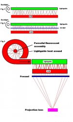
Fig 1 shows a typical edge lit LCD. Light comes in from a thin cold cathode fluorescent type lamp. Goes into a lightguide which spreads the light across the rear of the LCD and allows it to go forward.
Fig 2 shows the same thing but with a 3M Brightness Enhancing Film sandwiched between the lightguide and the rear of the LCD. Its purpose is to straighten up the light so you get more light going forward giving a brighter LCD with a smaller viewing angle.
Fig 3. Light processes are reversible. This is handy and if we took an LCD lightguide and bent it around an LOA tube or several or some other very powerful fluorescent combination it might be possible to collect a far greater amount than from a regular reflector and then channel that light into your LCD backlight and provide enough light for projection.
Lightguides rely on total internal reflection eg If you get a piece of perspex say 1/8 inch thick with highly polished surfaces and highly polished edges and you shine a light into one edge, all the light stays inside the perspex and does not come out. If you then scratch one surface some light will exit at that point. So I am thinking it should be possible to bend a piece of perspex around and score the surface on the inside. The light from the fluorescent combination should enter the perspex and not come out except at the exit port. This needs research but it could be a viable method and its quite cheap
It has been done. Some people report success, others say not enough light.
If LOA was 100 percent succesful everyone would use them because there are so many advantages.
Its just getting all the light to go in the right place that is a problem.
The drawing might help.
Fig 1 shows a typical edge lit LCD. Light comes in from a thin cold cathode fluorescent type lamp. Goes into a lightguide which spreads the light across the rear of the LCD and allows it to go forward.
Fig 2 shows the same thing but with a 3M Brightness Enhancing Film sandwiched between the lightguide and the rear of the LCD. Its purpose is to straighten up the light so you get more light going forward giving a brighter LCD with a smaller viewing angle.
Fig 3. Light processes are reversible. This is handy and if we took an LCD lightguide and bent it around an LOA tube or several or some other very powerful fluorescent combination it might be possible to collect a far greater amount than from a regular reflector and then channel that light into your LCD backlight and provide enough light for projection.
Lightguides rely on total internal reflection eg If you get a piece of perspex say 1/8 inch thick with highly polished surfaces and highly polished edges and you shine a light into one edge, all the light stays inside the perspex and does not come out. If you then scratch one surface some light will exit at that point. So I am thinking it should be possible to bend a piece of perspex around and score the surface on the inside. The light from the fluorescent combination should enter the perspex and not come out except at the exit port. This needs research but it could be a viable method and its quite cheap
Attachments
I'd like to find a fibre optic sollution. With fibre attached along every edge of the light guide...all 4 sides. Perhaps even going a little further by having certain "areas" seperated from others for independant controll, ie: make the corners "dimable" incase you get "hot " areas due to the extra light concentrated in the corners. Anyone know the logistics of connecting fibre optics to the edge of the plastic light guide?
zardoz
zardoz
Spending some time at the 3M site I found some of this stuff that looks like it could possibly be used.
If you visit the following link you can see how they recommend its usage as an LCD backlight, which is essentially what we need to create, a really really bright backlight.
http://multimedia.mmm.com/mws/mediawebserver.dyn?rrrrrr9yJCFrL7Srd7Srrr2yFb4O0kAY-
I sent an inquiry in about pricing/samples of the stuff.. will see how they are about getting back to me. 🙂
If this could be used, maybe in conjunction with a light guide it may be possible to shrink the size of the projector considerably and still end up with better results.
Vikuiti™ Transmissive Right Angle Film (TRAF) is a dual purpose transparent optical film that redirects light toward the on-axis viewer in edge-lit systems. While in displays with multiple or serpentine light sources you can use the film as a beam splitter to create a more uniform light source.
If you visit the following link you can see how they recommend its usage as an LCD backlight, which is essentially what we need to create, a really really bright backlight.
http://multimedia.mmm.com/mws/mediawebserver.dyn?rrrrrr9yJCFrL7Srd7Srrr2yFb4O0kAY-
I sent an inquiry in about pricing/samples of the stuff.. will see how they are about getting back to me. 🙂
If this could be used, maybe in conjunction with a light guide it may be possible to shrink the size of the projector considerably and still end up with better results.
Hey hey! now were talkin ...just "tweak that bad boy" a tiny bit remp and we have a projector that run's off the sun 😉 During the day at least

remp said:
remp
How did we stray from your thread? Would ya like us to move this back there? ...it seems like we just sort of ran into your theory here
zardoz
How did we stray from your thread? Would ya like us to move this back there? ...it seems like we just sort of ran into your theory here
zardoz
Zardoz
I thought you might like that one.
Crash has got it sussed
If this could be used, maybe in conjunction with a light guide it may be possible to shrink the size of the projector considerably and still end up with better results.
Thats exactly right. None of this fiddling with huge bulbs and lenses and reflectors and such.
We got to get modern. Make a better mousetrap.
Zardos
Well if you think it is suitable why not just drop it in here. Its all to do with backlight stuff.
Well if you think it is suitable why not just drop it in here. Its all to do with backlight stuff.
As many know, analogue LCD monitors are coming down in price and approaching the $200 mark. It is now becoming economical to purchase a 14 inch or 15 inch LCD monitor and use it for a projection panel.
Advantages are
Modern technology
Easy interface to computer
Good resolution
Better light transmission characteristics than older projection panels
Ready availability
Relatively cheap.
With these advantages compared to projection panels one would think traditional 10 - 15 year old projection panels would be abandoned in favour of modern LCD monitors.
Traditional high end projection panels just as Sharp QA 2500 on Ebay have been sold at $500. Vga panels such as Nview Spectra C are close to $200 on Ebay and some models do not have video in, only computer in. Freight to areas outside the USA can be very high so if you live in an area outside the USA there is not only the panel cost and depending on your currency conversion ratio to the US dollar that can be quite high, but freight costs can make the whole purchase too expensive.
Desk mounted LCD monitors seem to be the natural succesor to projection panels and could be in widespread use already except for one serious problem.
Most LCD monitors have a pc board up one side of the panel, and a pc board across the top of the panel. The two boards are joined together by a short length of (usually brown ) flex cable.
This flex cable has to be lengthened to allow the two pc boards to be moved out of the way to allow a powerful external back light source to project the image.
It is not an easy job to lengthen the flex cable.
On this forum, of four known attempts to do this two have succeded and two have failed. In the case of the failures, the panels have become inoperative and unusable.
So the success ratio is not very high and it is unlikely to become higher because each individual attempt is usually a solo effort.
It did occur to me that it may be unneccessary to lengthen the flex cable at all, and the monitor could be used with only minor modifications.
Many modern LCD monitors have side mounted backlight(s) which direct their light onto a piece of prepared glass or plastic which pipes the light across the panel and directs the light forward and hence provides an illuminated panel.
If the side mounted light could be replaced by a much stronger light it may be possible to create a usable projector.
Many folk are using 400 w Metal Halide. It is a relatively simple optics matter to collect a portion of that light and turn it into a replica of the original LCD panel backlight.
In addition, as is well known, conventional lighting setups waste half their light output because LCD's only accept ploarized light of one particular polarization. This may be either the P polarizartion or the S polarization depending on panel details. The other polarization is simply wasted in heating the LCD first polarizer. This causes gradual clouding of the first polarizer and gradual dimming of the picture.
However many modern LCD monitors recycle the normally wasted 50 percent light by reflecting it several times from a very highly reflective mirror mounted behind the normal backlight assembly. The reflection causes a reversal of polarization and now the full output of the light is available rather than 50 percent.
It does need proven that replacing an LCD backlight with a much higher power unit would indeed result in a usable projector,
The advantages seem considerable and well worth further investigation.
**ow** my brain hurts is it me or do these plans look a bit comlex. nonetheless these plans are great. Great minds are at hand😉. what i plan to do is crazy and i understand that the chances are 50/50 of success/failure maybe less or more. as you guys might know, i plan to buy a high powered Opaque project and assemble/disassemble and make custom lighting and what ever i think may work. im optimistic 🙂 **On Topic** i plan to use LOas.
Goodluck to fellow Diy-ers!
-JimmY-
is it me or do these plans look a bit comlex. nonetheless these plans are great. Great minds are at hand😉. what i plan to do is crazy and i understand that the chances are 50/50 of success/failure maybe less or more. as you guys might know, i plan to buy a high powered Opaque project and assemble/disassemble and make custom lighting and what ever i think may work. im optimistic 🙂 **On Topic** i plan to use LOas.Goodluck to fellow Diy-ers!
-JimmY-
This link gives a very good set of pictures on how light pipes work
They make them with plexiglass or glass.
http://www.leutrek.com/LTK_P/LEDs/PhloxTechnology20020624sec.pdf
They make them with plexiglass or glass.
http://www.leutrek.com/LTK_P/LEDs/PhloxTechnology20020624sec.pdf
remp
remp you never cease to amaze me with the value and solid research of your post's. Without fail you dig out the nuggets (ever do any gold panning?) of knowledge that make the answers that much closer.
I think the 4 injection diagram in the data sheet is the answer, the light source to be determined....fibre optic, high intensity LED's or perhaps as disscused a HUGE light source collected and transmitted via lightpipes.
Excellant work!
zardoz (hit the return button at the wrong time 😱
- Status
- Not open for further replies.
- Home
- General Interest
- Everything Else
- The Moving Image
- DIY Projectors
- Step into the Light.....