Mouser Electronics - Electronic Components Distributor
Should do fine, at least that's what I'am ordering, for T6 I will use MPSA06.
Referring to the datasheet, it's important tu order the "C" suffix version, otherwise you wil end up with an E-B-C part...not point in buying a fancy PCB if it's to fit trannies with tortured leads..
I bought the soft start and speaker protection boards from the DIY store. 2sc945, another obsolete transistor.
Should do fine, at least that's what I'am ordering, for T6 I will use MPSA06.
Referring to the datasheet, it's important tu order the "C" suffix version, otherwise you wil end up with an E-B-C part...not point in buying a fancy PCB if it's to fit trannies with tortured leads..
Attachments
Last edited:
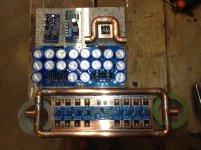
Well, I have all the boards done: Both channels, the power supplies, soft start and the speaker protection. Now, all I need is the toroid, case, plumbing, radiator, fans, thermal controller............I'm thinking that this is the fiscal half-way point.
Attachments
As far as toirod selection goes, would it be a better idea to have one AN-15432 or two AN-6232s?
http://www.antekinc.com/pdf/AN-6232.pdf
Antek - AN-15432
http://www.antekinc.com/pdf/AN-6232.pdf
Antek - AN-15432
Dual transformers and dual PSUs are best option. Next is large single transformer with 4 set of windings and two PSU's. Then single toroid and psu.
Mono-block is best provided the regulation of that single channel transformer has not been compromised such that it adversely affects performance.
2bz, your work so far looks great. I realize that this will put out a lot of heat but wont two 120mm computer fans for each heat sink blowing from outside cool it down enough. Just wondering why you chose the water cooled route.
2bz, I have these F5Tv3 PCB's also, but I didn't use them cause the MUR3020 diodes on the PCB are connected through a very small 0.5 mm 'via' from one side of the PCB to the other.
And I didn't think it would hold the large currents... Maybe you can solder a thicker wire across or something...
Sorry for informing you so late...
Walter
And I didn't think it would hold the large currents... Maybe you can solder a thicker wire across or something...
Sorry for informing you so late...
Walter
2bz, your work so far looks great. I realize that this will put out a lot of heat but wont two 120mm computer fans for each heat sink blowing from outside cool it down enough. Just wondering why you chose the water cooled route.
Both channels disipate a total of 600+ watts of heat. If you are going to do it, over do it.
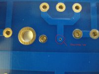
2bz, I have these F5Tv3 PCB's also, but I didn't use them cause the MUR3020 diodes on the PCB are connected through a very small 0.5 mm 'via' from one side of the PCB to the other.
And I didn't think it would hold the large currents... Maybe you can solder a thicker wire across or something...
Sorry for informing you so late...
Walter
Could you elaborate on this? Where on the PCb is this via? Thanks.
Could you elaborate on this? Where on the PCb is this via? Thanks.
See attached picture.
I don't know how much ampere can get through such a small hole. Maybe someone here knows?
Attachments
See attached picture.
I don't know how much ampere can get through such a small hole. Maybe someone here knows?
What if I were to drill it out to 2+
mm and then run a single strand of 2 mm copper wire from one side to the other and solder to the pads on each side?
Thanks for the heat sink info. That works out to almost a 3 foot section of 10 inch heat sink per channel using the c/w info provided at heatsinksusa unless I have got this wrong.
Multiple vias have lower impedance.
If lower impedance is required of this through board connection then the PCB designer should have included multiple vias.
Drilling a big hole through will not lower the impedance, it will only slightly lower the resistance.
Is there room on both sides to drill multiple 0.55mm through holes to solder in 0.5mm diam copper links?
Thanks for the heat sink info. That works out to almost a 3 foot section of 10 inch heat sink per channel using the c/w info provided at heatsinksusa unless I have got this wrong.
Per Mr. Pass, the optimal is 0.06 c/w. I was looking for a smaller solution. Plus I wanted to experiment with water cooling.
Multiple vias have lower impedance.
If lower impedance is required of this through board connection then the PCB designer should have included multiple vias.
Drilling a big hole through will not lower the impedance, it will only slightly lower the resistance.
Is there room on both sides to drill multiple 0.55mm through holes to solder in 0.5mm diam copper links?
I believe that 2 more small vias could be drilled.
I believe that 2 more small vias could be drilled.
Here are the results that I came up with for each of these particular vias:
Attachments

That sounds good, remember there are 7 of the 8 MUR3020's that have the 'via'....
2 more via X 7 diodes X 2 channels = 28 little holes/wires and 56 solder points!
- Status
- Not open for further replies.
- Home
- Amplifiers
- Pass Labs
- Starting to build my first F5 Turbo V3