Hello there
Well after several years missing in action I have found my way back here.
Previously I had planned and built an LM3876 pair of amps. Sadly all this was lost before it could be completed. Though working they needed an enclosure and proper speakers needed building.
So here I am again. No idea what my previous account name was but luckily I have found a few bits on a back up HDD.
I am hoping to be able to use my PCB patterns for this build. Though designed to suit the LM3876 it appears, with a minor change, that the LM3886 can be slipped into place. The main change being to connect pin 5 to +ve.
At the time of conception I had a lot of help, I remember, from AndrewT. Sadly I see he has passed on in the Intervening years. Rest well and thank you for all your help to the community and myself Andrew.
Here are the main parts I have recovered. The PSU PCB and associated regulators will need redoing. But that’s all.
Regards
Audible Click.
Attachments
I would go this route: An open source layout for LM3886?
Or this: LM3886 Done Right: Best DIY implementation of the LM3886 80W gainclone – Neurochrome
Bringing the power supply in from the left side will lower the supply impedance, which gives you lower chances of oscillation and better performance overall.
I also suggest making the pours solid rather than patterned. You might as well use the available copper. You're paying for it anyway...
Tom
Hello there
I have indeed seen both links whilst exploring and re-familiarising myself with the concepts.
My PCB is single sided and the hatching was to solve an issue with poor toner transfer quality when solid en massé black was done.
I have since found better materials to use as carriers and built a proper thermostatic controller to use with the texet laminator I nodded to transfer the patterns to the copper.
So I should be able to change to solid black transfer now. I may be able to revisit the layout of my PCB just to tighten it up some more. Though as the first pair worked this would just be “for fun”.
I continue to trawl the forums vast knowledge base and am ensuring I do the best I can with what I have.
Regards
AC
Another point: You'll want the connection between the quiet signal ground and the power ground at the speaker output (-) connector. You can see why here: Taming the LM3886 Chip Amplifier: Grounding – Neurochrome
Tom
Tom
Why single sided?
Can u plz share schematic of your regulators?
Hello there
Single sided mainly because that is what I am used to. I used to build a voice mod which was my first foray into doing PCBs at home. From design to etching, drilling and mounting components. I must have sold quite few in the years I was active and it was quite popular and successful within the niche market it was for.
It is tempting to have a go at double sided as the benefits are many.
Regards
AC
Another point: You'll want the connection between the quiet signal ground and the power ground at the speaker output (-) connector. You can see why here: Taming the LM3886 Chip Amplifier: Grounding – Neurochrome
Tom
Hello there
Do you mean move the end of the trace that comes from pin seven? Or the ground pad near its termination point? I am very rusty and was still learning much when I built my first pair.
Regards
AC
Can u plz share schematic of your regulators?
Sorry I forgot to address your second query.
You please see decibel dungeon website. It was based on the regulated schematic on their site.
Regards
AC
So here I am again. No idea what my previous account name was but luckily I have found a few bits on a back up HDD.
🙂
fooboo?
New amplifier...possibly..
It has been a while.
Hello there
Well, well, well. That was me 🤣😂🤣😂
Quite a while indeed. Much has happened in the intervening years. But I still had the need to build my own ‘system’ in the back of my mind. Fingers crossed this time.
Regards
AC
Which version?
Hello there
At this point, having perused the forum endlessly, I am re evaluating my possible direction.
Still an LM3886 based amp. But maybe I should just do the minimalist version. It has many fans I know just based on its sound. Also it would be somewhat more inexpensive with the reduced support components.
Smaller board, smaller enclosure. Thoughts?
Regards
AC
This is the highest quality sound I could get from LM3886 with split supply. Put it on small heat sink to allow it run at 70°C non isolated IC version.
You don't need a PCB, but two tiny ones that you can tailor by scalpel. The supply feet are plied upward to receive the capacitors and the mute resistor, the feet of the IC are not through hole but flat soldered. The signal feet are left flat, a second tiny PCB holds the feedback resistors, optionally the capacitor. The input transformer 24$ a pair comes with it's own PCB.
The pin1 is doubled by electrolytic capacitor lead soldered from root to PCB, the negative supply arrives at the tab, the pin 2 out+3NC are soldered at the root and on PCB together.
Attachments

Last edited:
Hello there
Thanks for the information.
I think I may go the gaincard route. There is one based around the LM3976 which I think I can use for the basis of an LM3886 version. Couple of extra pins and slight change in connections for the 3886. But basically should be as compact. I’ll draw up a PCB based on it and see how it looks.
Regards
AC
Hello there
Well I like making my own PCBs for one. ��
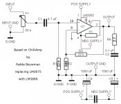
I think I have a viable circuit in the making. Basing it off of the Fedde Bouwman ‘Chill-Amp’ with the changes to suit the pin out of the LM3886.
Then it will be a choice of regulated or unregulated PSU. Regardless I will only be using a single toroid to drive both halves so that may dictate which variant is best suited.
Regards
AC
Well I like making my own PCBs for one. ��
I think I have a viable circuit in the making. Basing it off of the Fedde Bouwman ‘Chill-Amp’ with the changes to suit the pin out of the LM3886.
Then it will be a choice of regulated or unregulated PSU. Regardless I will only be using a single toroid to drive both halves so that may dictate which variant is best suited.
Regards
AC
When correctly designed 2 or more sides pcb will improve the amp performances compare to one side pcb.
Hello there
So I see from various posts on here. Though there seems to be as much variety in method as opinions. The chill amp, to my eye, seems to go against all I was told about grounding power and signal paths. But I am, in the audio field, a touch lost with the inception of said requirements.
It’s all a little black magic to me 😄 I’ll put up my version later and see what is thought of it then and tweak if needed to wring the best out of it.
Regards
AC
Hello there
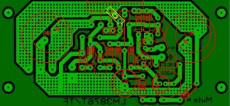
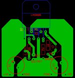
This is the PCB pattern and the amended schematic to suit the LM3886. The Board is around 2” square or thereabouts. An off board Theile network will be used. The component values will probably be taken from an LM3886 schematic.
The LM3886 will be mounted to on the trace side once the pins have been bent to suit. Two resistors will be mounted direct to the appropriate pins.
Regards
AC
Attachments
Last edited:
There are so many variations possible on this but a few things I would change...
1/ AC couple the feedback return. It is bad practice to DC couple and it will also cause higher than necessary offsets.
2/ A small air spaced coil at the output is good practice unless you can 100% guarantee any load attached would not cause problems.
3/ Add some kind of RF filter at the input.
4/ Doesn't the mute behave better with a suitable cap added? Look at the data sheet for examples.
Hello there
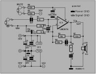
Thanks for the pointers. Having got to this point I think it will be easier to add the components required and tweak the layout to suit the additions. See the attached schematic which my original ‘working’ set up was based on. I think this has all the points you mention above covered.
Regards
AC
Thanks for the pointers. Having got to this point I think it will be easier to add the components required and tweak the layout to suit the additions. See the attached schematic which my original ‘working’ set up was based on. I think this has all the points you mention above covered.
Regards
AC
Attachments
- Home
- Amplifiers
- Chip Amps
- Starting again. LM3886 build.