Not wrong. The peak voltage at the crest of the sine wave is in the 530 volt range. More actually since Hammond transformers always put out more than their stated voltage. You will lose about 30 volts in the rectifier tube. The capacitor will charge up to the peak voltage if there was no load on it but the amp is discharging it all the time and the transformer is charging it only on peaks. You should get an average of 460 or so volts on the input cap, then you will lose another 20 in the resistor or choke for a B+ of 440 or so volts.
Look for a motor RUN (not start) cap in the 50 to 100 uF range rated for 370 VAC or more. It augments the 100 uF that is already there but it is also there for another reason. No capacitor is perfect, they have some resistance and inductance due to their construction. These unwanted traits are dependent on the type of cap and how it is manufactured. The characteristics of a motor run cap work to complement those of an electrolytic such that the combination works better than either alone.
I used to recommend a 560 ohm cathode resistor for just about all Simple SE amps, but with todays escalating line voltages and the ever increasing output of Hammond transformers a 620 ohm might be a better choice. Maybe 680 if you plan to run 6L6GC's most of the time. If you already have the 560 ohm, use them.
Strat,
Give PSUD a whirl. It's free and has generally predicted my output voltages very closely. The more parameters you set accurately, the more accurate it is (capacitor ESR and actual inductance at the operating point for inductors, for example). The main wildcard is the transformer, mainly when they put out way more voltage than expected.
http://www.duncanamps.com/psud2/index.html
Cool.tubelab.com said:Not wrong.
... You will lose about 30 volts in the rectifier tube. ... You should get an average of 460 or so volts on the input cap, then you will lose another 20 in the resistor or choke for a B+ of 440 or so volts.
ah ha! Makes sense. I'm used to embedded designs and switching regulators. The highest voltage I deal with is typically 5V - so it didn't even dawn on me that a tube would drop 30v and the choke 20...
Look for a motor RUN (not start) cap in the 50 to 100 uF range rated for 370 VAC or more.
Ok - but 370 volt rating on a 440v DC?
The characteristics of a motor run cap work to complement those of an electrolytic such that the combination works better than either alone.
Yup - we use tant's on USB power bypassing because they damp spikes when cables are inserted. Ceramics have such low ESR the inductance in the cable along with the cap causes nasty ringing.
I bought the 560ohm... Next time I do a digikey order I'll buy a few other values to try.
Thanks!
rknize said:Strat,
Give PSUD a whirl. It's free and has generally predicted my output voltages very closely.
Thanks - I'll check that out!
tubelab.com said:I used to recommend a 560 ohm cathode resistor for just about all Simple SE amps, but with todays escalating line voltages and the ever increasing output of Hammond transformers a 620 ohm might be a better choice. Maybe 680 if you plan to run 6L6GC's most of the time. If you already have the 560 ohm, use them.
I'll agree with that. I installed 560 ohm resistors in my Simple SE. I've got a Hammond 374BX power transformer. The 560 ohm resistors are perfect for KT88 output tubes, but if I run something else (6L6, 6p3s-e, 6CA7, EL34) I'll use 810 ohms instead. I get that value by adding a 250 ohm in series with the 560 ohm.
Another (better?) way to get different valued cathode resistances would be to use the 680 ohm that George suggests, and parallel with a 3K ohm resistor. 680 ohm in parallel with 3K ohm gives you ~560 ohms total resistance. The 680 ohm resistor needs to be rated for 5 watts, but the 3K ohm would be OK with a 2 watt or 3 watt rating.
oldmanStrat said:Ok - but 370 volt rating on a 440v DC?
Yep. Those specs are RMS AC volts. I think there is some extra safety margin in there too, but a 370V run cap should be good to at least 520V.
As far as the cathode caps, I found George's "Tubes and Transformers" chart to be pretty close to reality when you measure the actual plate voltage. Mine came it pretty much where I expected, but that was with the Edcor whose output was very close to the rating.
as soon as I posted that question the answer dawned on me...
hmmm, just checked my scope & probes. They are only good to 300v... hopefully I won't need to use one.
hmmm, just checked my scope & probes. They are only good to 300v... hopefully I won't need to use one.
Yeah my "scope" (if you can call it that) is only good up to 100V. It's a Velleman PCS500. I've actually used it a lot over the years and find that it does a pretty good job for most things, especially when you also have their frequency generator.
Anyway, I built a simple resistive 10:1 attenuator to allow me to measure higher voltages. It loads the source more than a single probe would, but it gets the job done.
Russ
Anyway, I built a simple resistive 10:1 attenuator to allow me to measure higher voltages. It loads the source more than a single probe would, but it gets the job done.
Russ
the build begins..
I received all of my parts on Friday, with the exception of the Edcor OPTs.
Couple of problems - both my own doing, first the channel coupling caps C11, C21 I had sourced on my own since I didn't want to do a separate Mouser order - and of course I didn't check the package size against the PCB. The vishay's were boxy and too short, and while I've made them fit - I might as well do this right.
So I'm probably going to bite the bullet and put in auricaps. Pretty pricey little buggers @ $10 for a .22uf, but luckily there are only two of them.
The second issue is that the 1500uf 6.3v caps for the voltage regs were backordered on Digikey until July! I have a source for 1800uf's or I can go to local parts guy and buy some 1000uf's...
Other than that the board went together easily.
I did find some transendar 5K opts on ebay - the pair went for $119, and I can get those pretty quick - so of course I pulled the trigger on those, so I can have some sound out of the amp while I'm waiting for the monster Edcors.
So this weekend I'll be building the box and cutting sheet metal for the switches, volume and inputs. With luck I'll be powering it on next weekend...
I'll be interested to see what you think of the Trancenders compared to the Edcor's.
I went with the Trancenders and couldn't be happier. But its nice to know I Can upgrade any time I want if I feel the need. So please post your thoughts on the two when you get to that point.
The Simple SE was my first ever DIY build and I thoroughly enjoyed it. Kudos to the tubelab for a great product.
Heres a link to my build if interested. http://www.diyaudio.com/forums/showthread.php?s=&threadid=138527
Have fun!
Nick
nikolas812 said:I'll be interested to see what you think of the Trancenders compared to the Edcor's.
I'm kind of curious myself. I'll be sure to post what I find when I hear them both.
The Simple SE was my first ever DIY build and I thoroughly enjoyed it. Kudos to the tubelab for a great product.
It's my second, but this one is by far a better learning experience. Seconds to the kudos!
Heres a link to my build if interested. http://www.diyaudio.com/forums/showthread.php?s=&threadid=138527
I read your thread before I decided to buy the Simple SE. I had seriously considered the Hagerman Cymbal monoblocks (the parts alone added up to $1100!!) and a Decware kit ...
Hagerman was too pricey, and the Decware stuff - well I kind of felt like I was being oversold. You know that feeling you get when you walk into a car dealership?
The bottlehead S.E.X amp nearly got me too - but it just seemed a little whimpy compared to what I could build with the Tubelab iron...
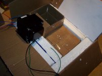
Here are a couple of pics of the build so far
hmm - looks like one attachment per message.
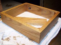
This is the box - red oak 1" thick (actually 2cm). The center support isn't glued, I'll be attaching the choke to this support as well as the fuse, current limiter and misc wires.
hmm - looks like one attachment per message.
This is the box - red oak 1" thick (actually 2cm). The center support isn't glued, I'll be attaching the choke to this support as well as the fuse, current limiter and misc wires.
Attachments

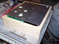
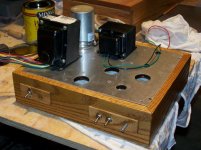
NBD. If you look at the right edge of the photo, you'll see where I had to cut out a notch in the wood frame for the RCA input jacks. This was by design - given the small size of the aluminum top plate, I wanted as much real estate as I could muster. Putting the RCA jack slightly over the frame bought me an extra quarter inch, which made the spacing around the binding posts (at the other side of the plate) a little more comfortable.

Yes, it's not a big deal... I'll get to it before I start the wiring.
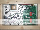
Finished the holes in the top cover - plastic is still on the aluminum, but I'm really hoping it is still pretty clean.
The IEC connector has built in line filtering - which I thought couldn't hurt. The speaker connectors will be screwed into the wood ... believe it or not this works pretty well and is very sturdy.
I need to make plates for the inputs, and the front panel (volume, switches and power light). I've decided that a machine shop can spit these out pretty quick and anything I do I'm probably not going to be happy with.
Attachments
pic update of the day
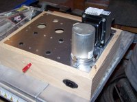
Figured out how to mount the front switches - the blank hole is for a power led. I have a nice one that looks like it belongs on a guitar amp, but it uses 6V, and I'd rather not hack up the board for the DC...
So I'll go to the shack for a red AC light.
Figured out how to mount the front switches - the blank hole is for a power led. I have a nice one that looks like it belongs on a guitar amp, but it uses 6V, and I'd rather not hack up the board for the DC...
So I'll go to the shack for a red AC light.
Attachments
Have you given any thought to having the mounting bracket for the motor run capacitor mounted underneath? I think it would really clean up your chassis. Otherwise I really like the look of what you have going on! Nice job.
thanks!
I'm not sure what you mean by mounting the MR cap bracket under the chassis. Right now the clamp holds 2 L brackets which are screwed to the top plate.
I was thinking that I could spray paint the MR cap black to match the transformers... might make things a little more pleasing and very easy to do.
I'm not sure what you mean by mounting the MR cap bracket under the chassis. Right now the clamp holds 2 L brackets which are screwed to the top plate.
I was thinking that I could spray paint the MR cap black to match the transformers... might make things a little more pleasing and very easy to do.
- Status
- Not open for further replies.
- Home
- More Vendors...
- Tubelab
- Starting a Simple SE build...