I want to build a line stage preamp, using a mu follower circuit, with ecc88 tubes.
However, this is my first tube build, so I thought it would be best to build
a low voltage line stage preamp first - using ecc86 (6gm8) tubes.
The issue of how to run Star Grounding for the audio ground comes up.
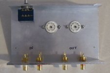
If you look at the photo, I was thinking of using the shields from the input RCA's,
as the star ground node.
Both input shields would be connected together to form the audio ground node.
So the power supply ground, tube amp ground, output RCA ground (shields)
would all be connected together at that point.
Hopefully this is correct.
From what I have read, heaters should always have a DC connection to audio ground.
I have decided to use DC for the heaters.
Then the aluminum case would be connected to Hydro Earth.
.
However, this is my first tube build, so I thought it would be best to build
a low voltage line stage preamp first - using ecc86 (6gm8) tubes.
The issue of how to run Star Grounding for the audio ground comes up.
If you look at the photo, I was thinking of using the shields from the input RCA's,
as the star ground node.
Both input shields would be connected together to form the audio ground node.
So the power supply ground, tube amp ground, output RCA ground (shields)
would all be connected together at that point.
Hopefully this is correct.
From what I have read, heaters should always have a DC connection to audio ground.
I have decided to use DC for the heaters.
Then the aluminum case would be connected to Hydro Earth.
.
Attachments
Last edited:
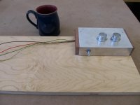
To add, I made the case by cutting a spare piece of 4 x 4 x 0.100" Architectural aluminum.
The inputs were kept away from the outputs.
Drilling the 0.850" holes for the tube sockets was a @#&% !
I don't want AC anywhere inside the shielded case, so I'm running DC for the heaters.
Here is the schematic for the ecc86 (6gm8) line stage.
Line Preamplifier battery powered
I think its an SSRP.
With a 24 Vdc rail, the bias measures at just over 1 mA,
which seems a little low.
Think I'll run it with a 30 Vdc or 32 Vdc supply.
.
AC heaters really are OK if you twist the wires (I use a power drill and a pair of pliers for that), route them close to the casing and away from input signal wires, etc. But whatever.
You say "Both input shields would be connected together to form the audio ground node." but this does not describe a star ground.
In a star ground, just one of those ground lugs would serve as the star.
Perhaps you mean a ground bus? A star ground is technically a bus anyway.
You say "Both input shields would be connected together to form the audio ground node." but this does not describe a star ground.
In a star ground, just one of those ground lugs would serve as the star.
Perhaps you mean a ground bus? A star ground is technically a bus anyway.
Basically it's not clear where power comes into the circuit. You should base your star (or bus) ground on where the power supply filter network ends.
The input phono's represent a poor choice to base your Star Ground on. A separate case bolt somewhere in the middle of the case is a better approach. Every earth wire then get taken to this bolt by tags.
Shoog
Shoog
DC heaters are not necessary for a line stage, and may cause extra problems.
Most newbies trying to implement a star ground ensure buzz by including the star ground in the PSU charging pulse loop from the power transformer secondary via the rectifiers. Others confuse signal ground and safety ground by using tags on a chassis bolt as their star.
Pick a point and call that signal ground. The output of the PSU is as good a place as any. Connect the input socket outers and the output socket outers to that point via the input and output cables, respectively. These cables should be shielded/screened so use the screens as the ground connection; some may tell you to use twisted pairs - you can get away with this in a grounded metal chassis. Make your circuit.
Connect the chassis to the incoming mains ground. At a separate point, connect a wire from the signal ground to the chassis; if this creates a ground loop then you may need to do something more complicated.
I usually connect the signal and mains ground (chassis) using pair of high current yin-yang diodes.
I usually connect the signal and mains ground (chassis) using pair of high current yin-yang diodes.
Ditto, but with a small R (typically 100R or so) and a small C (1nF) in parallel with the diodes.
Ditto, but with a small R (typically 100R or so) and a small C (1nF) in parallel with the diodes.
Also, make sure you remove the anodizing from the area of the case ground connection. The anodized aluminum is a poor conductor.
Also, make sure you remove the anodizing from the area of the case ground connection. The anodized aluminum is a poor conductor.
May or may not be clear anodized but aluminum also oxidizes instantly and invisibly. A good star-type lock washer might be enough to pierce any of that.
Thank you for your responses.
There doesn't seem to be much info on this topic.
That's why I introduced this thread.
Hopefully, this will be a resource for the topic.
The circuitry for the amp will be inside a shielded box
and the power supply will be on the outside of the box sitting on the plywood.
I think it would be best to have the audio star ground node inside the shielded box.
If the shields of the input cables is not the best place,
how about at the -Ve of the bypass capacitor that is connected between B+ and the -Ve ?
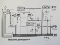
Looking at the schematic of the Mambo Amp - it implies a similar set up - power comes from outside the circuitry area.
But of course, the Mambo uses a Copper plate for the audio ground node.
Note too, the DC path between the one heater wire and audio ground.
In this case, the 68K and 221K form a voltage divider to lift the heater voltage.
There doesn't seem to be much info on this topic.
That's why I introduced this thread.
Hopefully, this will be a resource for the topic.
The circuitry for the amp will be inside a shielded box
and the power supply will be on the outside of the box sitting on the plywood.
I think it would be best to have the audio star ground node inside the shielded box.
If the shields of the input cables is not the best place,
how about at the -Ve of the bypass capacitor that is connected between B+ and the -Ve ?
Looking at the schematic of the Mambo Amp - it implies a similar set up - power comes from outside the circuitry area.
But of course, the Mambo uses a Copper plate for the audio ground node.
Note too, the DC path between the one heater wire and audio ground.
In this case, the 68K and 221K form a voltage divider to lift the heater voltage.
Attachments
Yeah, some people believe that they can improve the sound of a preamp by moving the power supply further away.
It's not really a terrific idea, particularly when it means you have a high voltage power supply cable running between two boxes. Connectors that are actually rated for that kind of duty are expensive and unusual, and most amateurs don't bother to use them, but still want a connector rather than a captive cable. These setups can kill people.
Near as i can tell, what they are hoping for is to minimize is low-frequency EMI from transformers.
There are an awful lot of good designs that don't incorporate such things, from which you should be able to infer that it isn't required.
At any rate, a piece of aluminum isn't going to block the magnetic field coming off of a transformer. And a power supply filter network (capacitors, resistors, inductors, etc) aren't going to induce signals into their neighbors.
Additionally, AC theory tells us that the power supply filter network is indeed part of the audio signal circuit.
A lot of people don't really understand how a shield and a signal return and a ground reference aren't necessarily the same thing. Or that your 'shield' or 'ground' or 'signal return' can carry unwanted signals into your circuit. But i don't think we need to go into that just yet.
There are a lot of people in this forum who are a lot more knowledgible and experienced than i am, but this is how i would proceed if i were you:
1: Complete the enclosure so that the power supply iron and power wiring is where it is going to be when the circuit is considered complete.
2: Build the circuit, except for the ground.
3: Keeping in mind that parallel wires induce signals into each other and perpendicular wires really don't (much), pick a spot on the amp chassis that looks convenient, drill a hole, run a screw through it, secure it with a nut and a star washer, and start attaching grounds to it.
We should probably have a sticky for grounding topologies. A lot of forums do.
Yeah, some people believe that they can improve the sound of a preamp by moving the power supply further away.
Rather than buying a case, I had this small piece of 4 x 4 x 0.100" architectural aluminum kicking around.
I thought it would be good because it would keep current loops quite small.
Especially - there wouldn't be a long wire from the input RCA's in the back
to the volume control at the front, and then another long wire from the volume control to the grid resistor.
It's not really a terrific idea, particularly when it means you have a high voltage power supply cable running between two boxes. Connectors that are actually rated for that kind of duty are expensive and unusual, and most amateurs don't bother to use them, but still want a connector rather than a captive cable. These setups can kill people.
If all the circuitry is the in the same box, typically there is a shield plate between the power supply area and circuit areas.
Wires passing through or near the edges of a metal plate without a grommet to protect them, is not good either.
Near as i can tell, what they are hoping for is to minimize is low-frequency EMI from transformers.
I did this to keep wire lengths short in the circuit area.
Even though this is just in the audio frequency range, its probably not a good idea
to have long wire lengths transmitting to each other.
Also, in a small box like this P to P wiring can be done.
Also, note how I kept the inputs well away from the outputs.
The last I wanted was some oscillation ("singing") occurring.
You'll see RF guys building circuits in small boxes made of FR-4.
But of course this is done to shield the circuit from RF signals and EMI.
The wiring is P to P and the power supply is on the outside.
There are an awful lot of good designs that don't incorporate such things, from which you should be able to infer that it isn't required.
At any rate, a piece of aluminum isn't going to block the magnetic field coming off of a transformer. And a power supply filter network (capacitors, resistors, inductors, etc) aren't going to induce signals into their neighbors.
Additionally, AC theory tells us that the power supply filter network is indeed part of the audio signal circuit.
The beauty of circuits such as a SSRP and mu follower is that the top triode forms a constant current source. This improves the amp's PSRR.
A lot of people don't really understand how a shield and a signal return and a ground reference aren't necessarily the same thing. Or that your 'shield' or 'ground' or 'signal return' can carry unwanted signals into your circuit. But i don't think we need to go into that just yet.
Well, I was going to ask, if the Hydro Earth is connected to the metal case,
does is usually induce noise into the circuit ?
There are a lot of people in this forum who are a lot more knowledgeable and experienced than i am, but this is how i would proceed if i were you:
1: Complete the enclosure so that the power supply iron and power wiring is where it is going to be when the circuit is considered complete.
2: Build the circuit, except for the ground.
3: Keeping in mind that parallel wires induce signals into each other and perpendicular wires really don't (much), pick a spot on the amp chassis that looks convenient, drill a hole, run a screw through it, secure it with a nut and a star washer, and start attaching grounds to it.
Shouldn't the metal case be connected to Hydro earth
and the audio ground be a node inside the case ?
Absolutely - I looked for some info and couldn't find much.We should probably have a sticky for grounding topologies. A lot of forums do.
Rather than buying a case, I had this small piece of 4 x 4 x 0.100" architectural aluminum kicking around.
I thought it would be good because it would keep current loops quite small.
Especially - there wouldn't be a long wire from the input RCA's in the back
to the volume control at the front, and then another long wire from the volume control to the grid resistor.
OK. So where does the power supply go?
If all the circuitry is the in the same box, typically there is a shield plate between the power supply area and circuit areas.
I find that this is rarely true, unless a band of high-permeability foil around the windings of the transformer counts.
Wires passing through or near the edges of a metal plate without a grommet to protect them, is not good either.
For fire safety reasons, yes.
I did this to keep wire lengths short in the circuit area.
Even though this is just in the audio frequency range, its probably not a good idea
to have long wire lengths transmitting to each other.
Also, in a small box like this P to P wiring can be done.
Also, note how I kept the inputs well away from the outputs.
The last I wanted was some oscillation ("singing") occurring.
That's less likely to happen than you think.
You'll see RF guys building circuits in small boxes made of FR-4.
But of course this is done to shield the circuit from RF signals and EMI.
The wiring is P to P and the power supply is on the outside.
RF is a bit of a different beast. And you meant copper-clad fr4, since fr4 just refers to glass & epoxy board. The magnetic permeability of aluminum is not very high, and copper is even lower. And by keeping the power supply components separate, the most you could possibly accomplish is to keep EMI at bay.
If you are using an EI-core power transformer, those do a pretty good job of rejecting interference that comes in from mains power. If you are using a toroidal transformer, those are wide-band devices, and you will want to use a common mode choke on the mains side.
Faraday cages are another subject, constructed to block RFI, and i can assure you that you're not building one. The good news is that a well-designed audio-frequency circuit should be able to reject radio-frequency interference without any special shielding.
The difference between a faraday cage and a big antenna drawing undesirable signals into your circuit can be very subtle.
Well, I was going to ask, if the Hydro Earth is connected to the metal case,
does is usually induce noise into the circuit ?
Shouldn't the metal case be connected to Hydro earth
and the audio ground be a node inside the case ?
I'd forgot that you had planned to earth the chassis. So you'll want to isolate the star from the chassis and use a ground loop breaker. Or use a length of solid copper wire, 14ga or 12ga perhaps, as a ground bus. the end of the power supply filtering network should connect to ground at one end of that bus.
For a ground breaker, create a circuit of two 1n4007 in series from signal ground to earth, paralleled with another pair from earth to signal ground, paralleled with a small capacitor and a resistor in series.
Last edited:
Thank you for your responses.
There doesn't seem to be much info on this topic.
But there is, right under your nose 😉 Check the Articles section here to find a wonderfully comprehensive article on Grounding by David Davenport. I printed it off years ago and use it as a reference.
Also find in the archives a thread about Thorsten Loesch's DIY phono design as built by Kofi Anan. Thorsten gives step by step instructions suitable for a beginner.
Another option would be an isolated chassis-mount turret, like this:
Insulated Green Diallyl Star Ground Turret Terminal 4 40 Thread Chassis Mount | eBay
But really. The key to good grounding is going to be the power supply, not the input jack.
Insulated Green Diallyl Star Ground Turret Terminal 4 40 Thread Chassis Mount | eBay
But really. The key to good grounding is going to be the power supply, not the input jack.
Ground loop breakers are only useful at the beginning and end of the audio chain (e.g. CD player and power amp). There's no need to use one in an intermediate preamp.
Possible grounding guidelines
Hi,
Perhaps this article can be of help. And I as well think there could be some more 'graphic' or visual guidelines and implementations of earthing techniques.
Most given information is verbal/written and can sometimes be confusing. And I would like to learn more as well.
Especially, although 'off-topic', earthing implementations in integrated tube amps when using SE transmitter tubes (211, 845, 805).
Regards, Stef.
Here is the link: Grounding and Shielding for your DIY Audio Projects
Which topic? Lots of info on audio grounding; some of it is even useful!Uunderhill said:There doesn't seem to be much info on this topic.
That's why I introduced this thread.
Hopefully, this will be a resource for the topic.
Typically only when the designer does not know what he is doing.If all the circuitry is the in the same box, typically there is a shield plate between the power supply area and circuit areas.
Not really. SRPP PSRR is -6dB; quite poor. Mu follower is better, but not necessarily hugely better.The beauty of circuits such as a SSRP and mu follower is that the top triode forms a constant current source. This improves the amp's PSRR.
That is not the way to twist a pair of wires. But it is quick and wrong !AC heaters really are OK if you twist the wires (I use a power drill and a pair of pliers for that).........
Use your hands to twist the wires and allow the individual cores to rotate in the opposite direction to your twisting direction.
It is this contra-rotating turn of the cores that allows the twisted pair to form correctly.
I usually use a door knob to anchor the fixed end, but a bench mounted vice would do a better job.
- Status
- Not open for further replies.
- Home
- Amplifiers
- Tubes / Valves
- Star Grounding for a Line Stage Tube Preamp