I was commenting strictly problems with A1 circuitry
didn't invest much time in other examples mentioned here , except fact that they're having pot in NFB loop
didn't invest much time in other examples mentioned here , except fact that they're having pot in NFB loop
Ooooh....
Well, then the gain skyrockets...
Somebody's obviously had this thought before. Any way of remedying that?
No, if the wiper get off, there's no input signal ;-)
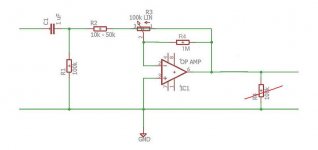
A large R to ground from the input will not impact control by prevent the offset to skyrocket when the wiper lifts.
Jan
This is imho the way to do things.
You need no capacitor on the output, voltage there allways zero.
To prevent circuit to be offset by an input voltage the capaitor should be there.
A resistor from the out to the minus-in keeps the output at ground level if the wiper fails.For OpAmps with fet input it may be much larger (10M).
And don't forget, the input series resistor includes the output resistance of the source.
Mona
Attachments
Last edited:
Thanks for the great input Ketje.
De-coupling cap for an inverting op amp is different from a non-inverting. Updated circuit below.
Now the question is if I should have a non-inverting buffer in front of it. Both for impedance reasons and making sure the thing is quiet when it's not powered.
Total component count for a stereo version is now ten, using a dual linear pot, a dual op amp and the two op amp bypass caps not shown in the drawing.
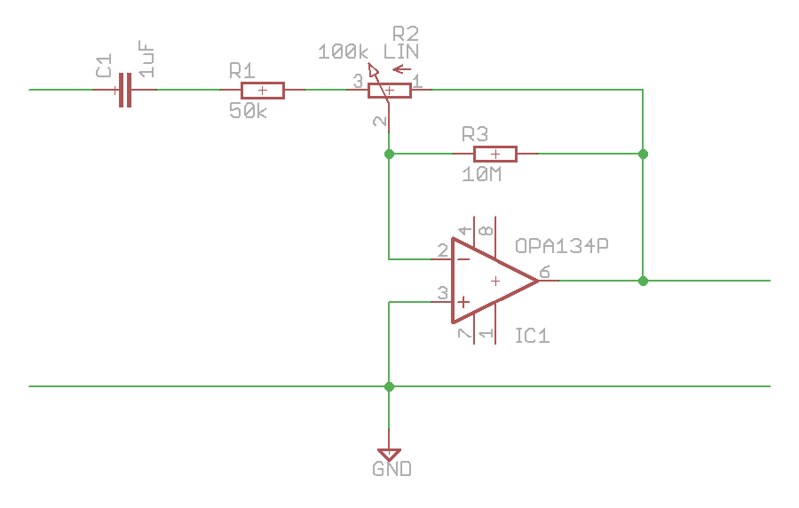
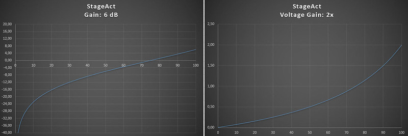
I'm using R1=50k ohm, which gives a max gain of 6 dB and a cut-off frequency (-3 dB) of 3.18 Hz.
Here are the gain curves, dB and voltage, from 0 to 100% turn of the pot:
De-coupling cap for an inverting op amp is different from a non-inverting. Updated circuit below.
Now the question is if I should have a non-inverting buffer in front of it. Both for impedance reasons and making sure the thing is quiet when it's not powered.
Total component count for a stereo version is now ten, using a dual linear pot, a dual op amp and the two op amp bypass caps not shown in the drawing.
I'm using R1=50k ohm, which gives a max gain of 6 dB and a cut-off frequency (-3 dB) of 3.18 Hz.
Here are the gain curves, dB and voltage, from 0 to 100% turn of the pot:
You can also get rid of that fat capacitor like this 😀
An important thing to remember also is, you must use an op-amp that is unity gain stable for this kind of circuits.
Mona
Yes,
My question was sorta hidden in there.
I wondered if I should add a buffer in front of the circuit. Partly for impedance reasons, and partly for making sure the thing is quiet when the opamp isn't powered.
Still, there's the DC component to worry about. Isn't it? Won't that buffer happily amplify any DC fed into it?
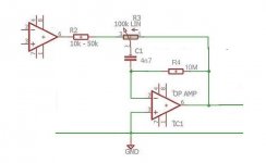
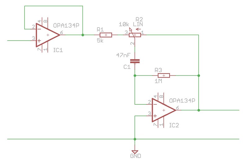
How about this? The cut-off frequency is 1.59 Hz:

An OPA2134, for instance, should be unity gain stable with proper use of bypass capacitors. Having a gain of 2x would absolutely fix any instability problems, giving the circuit a total max gain of 12 dB.
With a capacitor between the wiper en the minus-in, no problem with DC, without the offset from the driver is amplified by IC1.
And at volume zero, wiper on the right stop, the gain of IC1 is 1x !
Mona
And at volume zero, wiper on the right stop, the gain of IC1 is 1x !
Mona
Ah, of course!
I didn't notice that capacitor 🙂
Is this better?

Will the 10M resistor act as a DC return path for the 4n7 cap?
I didn't notice that capacitor 🙂
Is this better?
Will the 10M resistor act as a DC return path for the 4n7 cap?
Should do for a FET input OP; a bipolar one may require something substantially lower in value. Typical input bias current for a bipolar is in the order of 50-500 nA, and even a part with cancellation circuitry may not be any less critical (e.g. LM4562 start-up trouble in single-supply applications).
The 10M resistor sets the DC condition for IC1.Without it the input floats.
@sgrossklass, look at post 23 !
Mona
@sgrossklass, look at post 23 !
Mona
- Status
- Not open for further replies.
- Home
- Amplifiers
- Solid State
- StageAct - Four components Preamp