If the problem follows the tubes then the problem is weak tubes. You all ready mentioned that you ordered a couple of new sets, right? If you have them, put them in and set the bias. That should solve your problem.
Question - other than the bias not setting, is the amp completely operational and sounding good?
Question - other than the bias not setting, is the amp completely operational and sounding good?
If the problem follows the tubes then the problem is weak tubes. You all ready mentioned that you ordered a couple of new sets, right? If you have them, put them in and set the bias. That should solve your problem.
Question - other than the bias not setting, is the amp completely operational and sounding good?
yeah it's sounding great but these tubes dont have much time on them as far as i know. i got them new with the kit and only have about 100 hrs on them if that. i have installed SED russian tubes and they are strong. if the bias voltage drifts does that mean the tube is getting weaker? why does the tube get weaker prematurely, voltage too high?
im thinking about getting one of those current probes off of ebay. you advise that this is a good idea?
The bias in my stock 70 drifts for about 15 min., but I have old original 6CA7. The bias also moves up or down on the opposite channel as the bias on one side is adjusted. You have to ping pong the adjustment until they balance at the desired voltage. That's normal for a stock 70.
On your good channel, does the bias pot give you a decent amount of spare range for adjustment? If so, when you swap the good tubes to the other side, do you get the same amount of spare range on the pot? If that is all good, I would double check the values of the Cathode resistors to see if they are still as required. If so, I would blame the tubes for the lack of biasing range.
Well, your tubes may of gotten hammered when you were having some of the earlier problems, or perhaps it's just a quality control problem at the tube factory. Hard to say.
Yes, voltage too high can damage a tube. Perhaps that's what happened to them...
You can get a current probe if you want one. However, if putting fresh tubes in the circuit makes everything happy, I would suggest just listening to it for a hundred hours or so and then seeing if the bias has drifted. Re-set it if it has, and just use the amp for another 100hr.
To answer some of your questions -
Changing the bias changes the current through the tube.
If the bias changes, it can mean that the tube is getting weaker, or just settling in a little.
How far away from optimal is the 'bad' set of tubes biasing? (What voltage should they read, and what are you getting?)
If you can bias one side, but not the other (Which I think is what you are saying),
Swap the set of output tubes from one side to the other. If the side you can (or can't) bias moves with the tubes, then that pair of tubes are the problem.
the bad tubes are about 30% from biasing, they read about .7 but should be 1 volt
im getting just under 390 volts to the plates now. is this good you think? this new rectifier is a massive tube. about twice as big as the gz34. looks kinda cool
Changing the bias changes the current through the tube.
If the bias changes, it can mean that the tube is getting weaker, or just settling in a little.
so increasing the bias voltage increases the amount of current through the tube? my thought is that it increases the grid voltage and reducing current but i think this amp is cathode biased so the higher the cathode voltage the less potential difference there is b/w grid and cathode causing higher current flow. ( i think)
I'm getting just under 390 volts to the plates now. is this good you think? this new rectifier is a massive tube. about twice as big as the gz34. looks kinda cool
Are you using the 5R4?
390v seems like a good voltage, it's definitely not too high!
Are you using the 5R4?
390v seems like a good voltage, it's definitely not too high!
it's 5r4wgy it has a large ceramic base and it's called a potato masher.
am i right about what i said about the biasing voltage?
it's strange. with the gz34 i get a perfect 420 volts. with the SS rectifier i now read 443 whereas i used to read up to 480volts. why are these readings all over the place like this.
Last edited:
IF you don't have a variac, you can use light bulbs, eg. 100watt in series with the power in. If it is very bright, you are drawing a lot of current, dim=little current. Without tubes you should see it bright and go dim as the caps charge. You should only be able to check B+ unloaded and bias range say -30 to -60 volts. leave it on the most negative value.....TO check the rest only put in the first stage tubes and verify their voltages taking in consideration the output are not there to suck a couple hundred miliamps out of the trans. If the voltages are about 30 volts high you should be OK. With the input shorted you should be able to verify the first stage and splitter are properly biased, ( close). Power down completely, install the output tubes, the heater should light and suck the transformer down a little more, adjust the bias on the outputs and try it out. If they do not bias, they are probably bad..
why are these readings all over the place like this?
Obviously, there will be a different B+ voltage with each of the rectifiers. The SS, 5R4, and GZ34/5AR4 all have different forward voltage drops.
However, the reason why the voltages vary with just one rectifier is load. The more load you have on the amp (mainly bias current) the less voltage you will get out of the transformer. Increase the bias and the B+ goes down. Unplug a couple of tubes and watch the B+ go way up. Ect... If you measure the B+ with no tubes installed (except the rectifier) it will be very high.
Depends on if you are talking about the voltage out of the bias adjuster pot or the voltage across the cathode R.am i right about what i said about the biasing voltage?
When you increase (make more negative) the voltage from the adjuster pot to the grid, you reduce current flow through the tube (or pair of tubes) and the voltage drop across the cathode R will reduce.
When you increase (make less negative) the voltage from the adjuster pot to the grid, you increase current flow through the tube and the voltage drop across the cathode R will increase.
Current through the tubes is proportional to the voltage drop across the cathode R's, so if you have a 10R shared cathode R between two tubes, and you are reading 1V across it, E=IR, I=E/R, and you are flowing 50ma through each tube (assuming they are reasonably matched). IIRC the ST-70 cathode resistors are 15 ohm, so keep that in mind when doing the math.
The different rectifiers have different forward voltage drops (different resistance).it's strange. with the gz34 i get a perfect 420 volts. with the SS rectifier i now read 443 whereas i used to read up to 480volts. why are these readings all over the place like this.
The plates of the EL34s have 410VDC on them so the idle Wattage is 41 Watts not the 43.5 Watts I stated earlier, my bad. 410VDC x 100ma = 41 Watts. So 41Watts divided by YOUR B+ will be your new idle current.
Craig
now i have a 5r4 rectifier and it gives me 390volts plate. i have the bias set at .85volts which with the 10R bias resistor gives about 43mA per tube.
43mA*390volts=17watts. el34 are rated at 25watts max plate
do you think this is a good set up? i want to run it a bit cool
You'll be down on max. power but other than that if it sounds good it is good. Many people use the 70% rule, bias the tubes at 70% of plate dissipation, which is 17.5 Watts, so you are right there.
Craig
Craig
You'll be down on max. power but other than that if it sounds good it is good. Many people use the 70% rule, bias the tubes at 70% of plate dissipation, which is 17.5 Watts, so you are right there.
Craig
why doesnt the SS rectifier drop the voltage more, it is supposed to be a direct replacement for the gz34. i would prefer to use it. can i pop it open and put a higher value resistor in it? with the gz34 i get about 430volts and with the SS about 460v
There's nothing wrong with running the SS rectifier, many of the old Dynaco based amps and mods used SS rectifiers. Using the same formula figure out what the current needs to be with whatever B+ the SS rectifier makes. One of the main reasons for using a 5AR4/GZ34 is to provide a warm-up for the tubes before B+ comes up. Using the 5R4 doesn't provide a warm-up time so you've already defeated that purpose, good or bad. I'm working on a friends ST70 and it came to me with a 5U4 which I don't think is a good idea as the filament draws 3A making the already hot PT hotter with less power out. I'm also building a pair of MK3s and I'll be using SS rectifiers because of the dreadful new GZ34s and FP capacitors that are available. If you do decide to run the SS rectifier makes sure the voltage doesn't exceed the voltage rating of the filter capacitors, a short period of overvoltage is probably OK though. There are many opinions about the new tubes but I keep thinking this, 20-30 years ago you would buy tubes throw them in and make whatever adjustments needed, now you throw the new tubes in and wonder how they are going to last. At least I had some time in the good old days.
Craig
Craig
Using the 5R4 doesn't provide a warm-up time so you've already defeated that purpose, good or bad. There are many opinions about the new tubes but I keep thinking this, 20-30 years ago you would buy tubes throw them in and make whatever adjustments needed, now you throw the new tubes in and wonder how they are going to last. At least I had some time in the good old days.
Craig[/QUOTE
i have a CL-90 unit installed to provide some warm-up time, i was advised to do this. why doesnt the 5r4 provide enough warm up time?
i read that it is better to run amps cooler because of the "iffy" quality of tubes these days. thanks a lot for your input. i wish i had been into this in the good old days, guess later is better than never. it's fun to tinker with tube amps, they sound good but they dont seem to be very reliable like SS is.
which voltage should i measure to determine the rating of the tank capacitors. i think they are rated for 250v
Last edited:
If you make a whisker of speaker wire grounded to chassis on a transformer coupled tube amp, you won't short the output transistor and dump the entire capacitor into the speaker, burning out the speaker. Neither if you overheat the tube will it destroy the speaker. Split supply direct connected transistor amps need about 3 protection systems including a SOA measuring sensor and microprocessor, disconnect relay, and SCR overvoltage shorter to be as safe around your expensive speaker as a transformer coupled tube amp.it's fun to tinker with tube amps, they sound good but they dont seem to be very reliable like SS is.
Speaking from ground zero in the midwest, tube amps are much more resistant to lightning strikes than the average transistor amp. I've had turn off capacitors blown, power switches blown, no damage to the transformer. Of course, the refrigerator probably took most of the stike, but transistor amps need a lot of mov's and such installed to be as damage free in a bad storm.
On seventies tubes and caps, my ST70 went on average about 10 years without tinkering. It would sweetly lose peak power and punch, not suddenly fail. My 1961 7199's tubes are original, no defect found. Two of the four 1961 12AX7's in the PAS2 are original, I'm using it tonight. All the tubes in one 1968 H182 organ are original, all the electrolytic caps were replaced. Four H182 tube sockets need replacing.
Last edited:
5R4 has a directly heated cathode(the filament) where as the 5AR4/GZ34 has an indirectly heated cathode and that's where the warm-up time comes from, the indirect heater. As far as reliability goes you have already experienced some unreliability from crummy parts but if that had been a Solid State amp you'd be changing a lot more parts than just a tube. Tube circuitry is many times more forgiving of mistakes, abuse, etc. Solid State usually goes in an instant with more smoke if there is a problem. Though the JJs sound good there is a big "wonder factor" on them, except maybe for the EL84.
Craig
Craig
On seventies tubes and caps, my ST70 went on average about 10 years without tinkering. It would sweetly lose peak power and punch, not suddenly fail. My 1961 7199's tubes are original, no defect found. Two of the four 1961 12AX7's in the PAS2 are original, I'm using it tonight. All the tubes in one 1968 H182 organ are original, all the electrolytic caps were replaced. Four H182 tube sockets need replacing.
wow that is amazing to read. do you think you can get this kind longevity with todays production tubes? what voltages are running on the st70 and what rectifier have you been using. i sweat whenever i turn my st70 on
5r4gwy in an st70
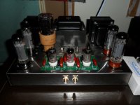
check this out. that is a potato masher.
The 5R4WGY is a high voltage power rectifier and was designed for transmitter use. It has a rating of 180 Watts. The maximum reservoir capacitor is specified at 4 µF and the rectifier needs a series resistance of 250 Ohms to limit peak current.
i now get just under 390 plate and so i run the amp at about 40mA/tube to keep things cool. still sounds good.
is this well advised? i know that there are often much differing opinions about mods.
Attachments
- Status
- Not open for further replies.
- Home
- Amplifiers
- Tubes / Valves
- st70 problem