480 on pin 1 of what? Is that only with rectifier installed?
Craig
with all the tubes. pin 3 is plate on the el34 power tubes and the voltage should be at 420v. (did i say pin 1? i meant pin 3). the voltage i read is 60v too high
Last edited:
What's the idle current now?
Craig
im afraid that you have gone over my head. the plate voltage i read is 480vdc so i guess that would mean 48 watts at 100ma. im not sure how to determine idle current or how to change it.
in a spec sheet it says that for class A/B operation the voltage should be 420vdc
thanks
Last edited:
What size resistor do you have on the cathodes of the EL34s? What is the voltage on the cathodes? Are they tied together?
Craig
Craig
the B+ voltage on pin 3 is about 480v and should be down around 420v. all other voltages check out slightly elevated. im using SS rectification and the mains voltage is slightly over 120. what is the best way to bring these voltages down?
i could use a variac or i guess i could install a resistor on the AC side of the PT someplace. can someone advice me what is best and show me how to calculate the resistance value and heat dissipation value of the resistor.
thanks
i could use a variac or i guess i could install a resistor on the AC side of the PT someplace. can someone advice me what is best and show me how to calculate the resistance value and heat dissipation value of the resistor.
thanks
Last edited:
the B+ voltage on pin 3 is about 480v and should be down around 420v. all other voltages check out slightly elevated. im using SS rectification and the mains voltage is slightly over 120. what is the best way to bring these voltages down?
i could use a variac or i guess i could install a resistor on the AC side of the PT someplace. can someone advice me what is best and show me how to calculate the resistance value and heat dissipation value of the resistor.
thanks
Go back to using a tube rectifier and add a 10R or 20R 20W power resistor at the secondary CT, not the primary side. 20W may be more than necessary but that is what I'd start with until you see how hot it gets. Fine tune the resistance value after you see the results with a 20R.
Go back to using a tube rectifier and add a 10R or 20R 20W power resistor at the secondary CT, not the primary side. 20W may be more than necessary but that is what I'd start with until you see how hot it gets. Fine tune the resistance value after you see the results with a 20R.
what is CT? do i connect it between the rectifier and the cap board?
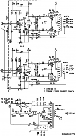
i attached a schematic for this amp. the power supply circuit is at the bottom. pin 8 leads to the cap board.
can you pls let me know where exactly i should install this resistor?
thanks
Attachments
what is CT?
Center Tap. It's the line to ground on the secondary. Put it in where the lines hook to ground.
It's easier than puting 2 individual power resistors, one on each line, to the rectifier. Your chassis wiring might make one big one impractical so the other way might be necessary.
Last edited:
What size resistor do you have on the cathodes of the EL34s? What is the voltage on the cathodes? Are they tied together?
Craig
there are 10ohm resistors and each channel has both tubes biased through one pot. i cant do any measurements now because i dont have a full complement of tubes. i only have 3 tubes. i guess it is alright to run one channel?
I would worry about getting the darn thing running before fine tuning the power supply voltages. If you don't have all the tubes to put in it your voltages are going to be higher than if the amp had all its tubes and was biased up correctly. No offense but I have an image in my mind that you don't have a clue as to what people are trying to do here to help you. You are asked a specific question and you come back with something else.
Do you have a 5AR4 or 5U4 rectifier tube and is it good? If so put it in and put tubes that you have in one channel.
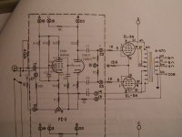
What tubes don't work/trashed? Take a look at the schematic I posted. Is it the same as the amplifier that you have? Are we dealing with an SDS Labs driver board that uses EF86 and 12AU7? Is the output stage wired the same as the schematic that I posted? Look at pin 8 on the EL34's on your amp. Is there a single 15.6 ohm resistor there or is there a separate resistor on EACH of the EL34's on pin 8? If the size of the bias resistor isn't 15.6 ohms what size is it? Let us know....😀
Have you ever set the bias? Take your meter and set it on Volts DC and measure ACROSS the bias resistor (the 15.6 or what ever value goes from pin 8 to ground) and let us know what the voltage is. Example 1.56 volts across the 15.6 resistor means you have 100mA bias for the pair of output tubes. If you happen to have a 10 ohm resistor then 1.00 volts across the resistor would give 100mA for the pair. Please take these measurements and post your findings. If your voltage across the cathode resistor(15.6) is less then adjust the bias pot for THAT channel until you reach the desired voltage.
Do you have a 5AR4 or 5U4 rectifier tube and is it good? If so put it in and put tubes that you have in one channel.
What tubes don't work/trashed? Take a look at the schematic I posted. Is it the same as the amplifier that you have? Are we dealing with an SDS Labs driver board that uses EF86 and 12AU7? Is the output stage wired the same as the schematic that I posted? Look at pin 8 on the EL34's on your amp. Is there a single 15.6 ohm resistor there or is there a separate resistor on EACH of the EL34's on pin 8? If the size of the bias resistor isn't 15.6 ohms what size is it? Let us know....😀
Have you ever set the bias? Take your meter and set it on Volts DC and measure ACROSS the bias resistor (the 15.6 or what ever value goes from pin 8 to ground) and let us know what the voltage is. Example 1.56 volts across the 15.6 resistor means you have 100mA bias for the pair of output tubes. If you happen to have a 10 ohm resistor then 1.00 volts across the resistor would give 100mA for the pair. Please take these measurements and post your findings. If your voltage across the cathode resistor(15.6) is less then adjust the bias pot for THAT channel until you reach the desired voltage.
I'll just add that most vintage tube amps - Dynacos especially - are easy to troubleshoot. Most of the time you don't need a scope, just a DMM, Ohms law and a dose of common sense.
Quote:
there are 10ohm resistors and each channel has both tubes biased through one pot. i cant do any measurements now because i dont have a full complement of tubes. i only have 3 tubes. i guess it is alright to run one channel?
If you have enough tubes for one channel go for it. Turn it on, bias up the channel come back with a report.
I've dealt with instructions to measure voltages without the tubes, in Bottlehead and Dynaco amps. What you are doing is matching up the manufacturer's experience with yours. It is good to know that you have an unloaded voltage that is within range of what is spec'ed, even though it is NOT what you'll get with the tubes in. I'm sort of dumbfounded that nobody here recognized this.
If a power supply is supposed to supply -55v bias voltage, and fully drawn it is 50, it is good to know that you have 55v and not 360v as might happen if you swapped the bias and B+ leads without blowing up your tube, or worse, swapping the filament and power leads.
I always check first without tubes, just to make sure I didn't majorly goof up.
Once you're sure you didn't swap leads or do something really stupid then put the tubes in and start taking the real measurements.
Quote:If you have enough tubes for one channel go for it. Turn it on, bias up the channel come back with a report.
i got 456v on pin 3 with the amp biased at 1volt. so i guess that is within tolerance. the filament voltage is about 6.5v so that is good too.
i guess the thing is operating properly. it just baffled me that i lost so many rectifiers, then a 10ohm cathode resistor and then a power tube. must have just been bad luck. also i didnt really understand the voltage/current/power dissipation problem related to the cathode voltage relative to the grid voltage biasing idea. so this caused anxiety and fear of the unknown.
im still going to try putting a 20r 20w resistor on the CT to bring the voltages down since i ordered it already.
so the total current draw of the amp is about 1.5amps? (mostly filament)
each tube pulls 50mA? 1v bias across one 10R resistor for two tubes is 100mA. is this correct? so how do you measure the total power dissipation? plate resistance times plate current gives voltage drop across the tube and current times plate voltage gives total power dissipation in watts?
is this correct?
thanks
There is a VERY simple way to reduce the B+ on an amp such as this, with no re-wiring or component swapping/trimming ---
Replace the rectifier with a 5R4. It has a 2 amp filament, only .3A more than the 5AR4, buy has a much greater forward voltage drop; 65v total or so, for a net loss (from the stock rectifier) of about 30v B+
They are cheap and plentiful, have the dissipation necessary for an amp like this, and in this modern day and age of wall voltages running higher than 40yr ago when the transformers were wound, a very easy way of trimming and adjusting your amp to work well.
There is a VERY simple way to reduce the B+ on an amp such as this, with no re-wiring or component swapping/trimming ---
Replace the rectifier with a 5R4. It has a 2 amp filament, only .3A more than the 5AR4, buy has a much greater forward voltage drop; 65v total or so, for a net loss (from the stock rectifier) of about 30v B+
.
does it requiring rewiring?
i got 456v on pin 3 with the amp biased at 1volt.
so the total current draw of the amp is about 1.5amps? (mostly filament)
each tube pulls 50mA? 1v bias across one 10R resistor for two tubes is 100mA. is this correct? so how do you measure the total power dissipation? plate resistance times plate current gives voltage drop across the tube and current times plate voltage gives total power dissipation in watts?
is this correct?
thanks
1V across a 10 ohm R for a pr of tubes is 50ma/tube, assuming that they are reasonably well matched.
Power is VI so your output tubes are dissipating 456V*.050A=22.8W; the max rated dissipation for EL34's is around 24W, so you are within limits. Note: the calculation above assumes triode operation, I have neglected the screen grid current, etc. Also note that I neglected the drop across Rk, since it's only 1V. For a cathode bias output, you need to subtract the voltage drop across Rk, since it's usually in the tens of volts range for typical output tubes. You want the voltage drop across the tube.
There is a VERY simple way to reduce the B+ on an amp such as this, with no re-wiring or component swapping/trimming ---
Replace the rectifier with a 5R4.
.....or a 5U4, also cheap and around 70V drop. Faster warm up than a 5AR4, though.
Last edited:
.....or a 5U4, also cheap and around 70V drop. Faster warm up than a 5AR4, though.
what about a 5y3 or a 5y4? can i use these in a st70 and get a higher voltage drop? i guess they require some rewiring? what is the diff b/w these two tubes
- Status
- Not open for further replies.
- Home
- Amplifiers
- Tubes / Valves
- st70 problem