The schematic is OK. Shows an optional Zener also that may had tricked you. Objectively yes, OSCON is a good filter. Subjectively not my preference there.
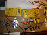
Red LEDs not lit
Hi all,
I just happen to be in the middle of a SSLV1.1 board PSU build for a standard Pass B1 Buffer PCB (the original from Pass Labs). Target voltage is +18V single rail.
I already built one successfully for my phono pre-amp and had no issues at all. But for this one, the two red LEDs in the voltage reference area do not light up. The 4 green LEDs do. I used the calculator to get the right parts (although I don't really know the load current), used 15R/5W for R301, 2 Wima Mks 4,7 uF Caps for C303 and C301, 1K8 for R303 and a Bourns W502 5K trimmer. D301 jumpered. I used BYV28-200 diodes for D311-314 as rectifier that I had lying around (instead of the MUR120). Nichicon Gold Tune 4700uF 100V as C305 (polarity is correct)
I had no visible signs of bad soldering, so I thought it would be good to build a second board with a different set of parts to be sure there is no bad part involved (I had a second board and IRF+ set on hand). Unfortunately with the same result.
Since building a shunt regulator with Salas and teabags boards for a B1 has been done loads of times in the community, could anyone give me a hint where I went for the wrong path?
Any help appreciated,
cheers
Most probably you are exceeding the CCS current with the load needed current, hence running into no juice for the shunt FET transistor.
I think the IRF9530 might be shorted. Measure voltages there, and all the T0-92 devices.
15R @ 18v should work, but 10R might be better if Roender is right.
15R @ 18v should work, but 10R might be better if Roender is right.
What is the dummy load used? That will say something certain about the set current sufficiency.
1R is effectively a short circuit. Thumbs up if with 2 surviving regulators, but to simulate a B1 make that 1K 1W.
Seems like we have found a source for my issues: myself. Thanks for your help, will see what I can rescue....
best
best
As Salas said, nothing was fried as short circuit protection is one of the many advantages for a shunt power supply. And it comes free with the design ;-)
Hi Salas, Roender and Tea-Bag
just did my reset and everything works like advertised. Thanks again...
just did my reset and everything works like advertised. Thanks again...
Quick question to the jfets selection.
The build guide says 3-5mA range, and it also says
My question is whether the 3-5mA range is the 9V testing reading,
or it is the prorated in-circuit IDSS?
For some reason, I have quite a few (50+% of a batch of 40pcs) at over 5mA IDSS using the 9V testing method. Can these be used by any means like at Q105?
Thanks!!
The build guide says 3-5mA range, and it also says
A circa 4ma IDSS 9V testing JET gives you around 3mA.
My question is whether the 3-5mA range is the 9V testing reading,
or it is the prorated in-circuit IDSS?
For some reason, I have quite a few (50+% of a batch of 40pcs) at over 5mA IDSS using the 9V testing method. Can these be used by any means like at Q105?
Thanks!!
Idss is the current passing when Vgs=0 and Tj=25degC
The in circuit current has Vgs not equal to zero, but some -ve voltage.
Inserting the resistor in the source, with gate to the ground side of that resistor creates that -ve Vgs and gives rise to Id<Idss.
The in circuit current has Vgs not equal to zero, but some -ve voltage.
Inserting the resistor in the source, with gate to the ground side of that resistor creates that -ve Vgs and gives rise to Id<Idss.
Quick question to the jfets selection.
The build guide says 3-5mA range, and it also says
My question is whether the 3-5mA range is the 9V testing reading,
or it is the prorated in-circuit IDSS?
For some reason, I have quite a few (50+% of a batch of 40pcs) at over 5mA IDSS using the 9V testing method. Can these be used by any means like at Q105?
Thanks!!
That's for IDSS on a battery out of circuit yes. Characterization for a parameter in other words. They can be used if you aren't planning a 40V+ reg. In an upper Vout range situation much current would make Q104 transistor hot (sinks Q105's feed, sees most of the voltage), Q102 hot by itself spanning the voltage distance to 4 LEDS potential. Still even in lower Vout range apps you should know that a strong Q103 will present higher voltage for same value voltage set trimmers and resistors. If it goes out of manageable revise resistance lower.
Thanks, Salas and Andrew.
I am about to start a 5V SSLV1.1 point-to-point wire build for JP's ES9023P Dac by
using the parts that I already have. My transformer is 9-0-9 which should work out to approx. 12.5VDC at C105. I think I am not at risk of overheating any transistors without major human mistake 🙂
I am about to start a 5V SSLV1.1 point-to-point wire build for JP's ES9023P Dac by
using the parts that I already have. My transformer is 9-0-9 which should work out to approx. 12.5VDC at C105. I think I am not at risk of overheating any transistors without major human mistake 🙂
SSLV1.1 has supply for tube heaters?
Dear all,
Has anyone tried to use BIB to supply undirected heated triode heaters? Say 6,3VDC (1A)
Thanks for your help.
Dear all,
Has anyone tried to use BIB to supply undirected heated triode heaters? Say 6,3VDC (1A)
Thanks for your help.
It is up and stable upon first switch, no BOO 😀Thanks, Salas and Andrew.
I am about to start a 5V SSLV1.1 point-to-point wire build for JP's ES9023P Dac by
using the parts that I already have. My transformer is 9-0-9 which should work out to approx. 12.5VDC at C105. I think I am not at risk of overheating any transistors without major human mistake 🙂
Next is to parallel a couple resistor to R101 and R103 to hit my 250mA and 5V mark then hook up to the dac ....
Attachments

Hi Salas
Do you have a JPG and/or PNG etc. of the BIBv1.1 schematic ?
I tried to extract the one from the PDF, but couldn't.
It would help me, as I like to type my own notes over it ( I don't have a printer ! ).
If you have such a picture file, posting it would help me a lot.
Thanks.
Si.
Do you have a JPG and/or PNG etc. of the BIBv1.1 schematic ?
I tried to extract the one from the PDF, but couldn't.
It would help me, as I like to type my own notes over it ( I don't have a printer ! ).
If you have such a picture file, posting it would help me a lot.
Thanks.
Si.
- Home
- Amplifiers
- Power Supplies
- SSLV1.1 builds & fairy tales