+4dBu professional standard is 1.228V RMS. About 12dB higher than consumer level -10dBV (0.316V).
In any case, for any level you want to convert from RCA to XLR without extra gain added, set between 2-3 output XLR pins double the voltage of the SE generator's input to the converter.
So if I get you right, the balanced signal out between 2 and 3 shall be double that of the generators input to SE for unity gain SE to bal. The Sonifex is opamp based with reference to PE so that makes me pretty sure that since I measured between 1 (gnd) and 2 (hot) it gave me the same result. Did I get you right?
I read this article before measuring but I am still a bit confused
https://lab2104.tu-plovdiv.bg/index.php/2019/02/28/voltage-measurement-of-balanced-outputs/
Optimal would be to solder up a 10k:10k transformer but it seems abit above and beyond
I read this article before measuring but I am still a bit confused
https://lab2104.tu-plovdiv.bg/index.php/2019/02/28/voltage-measurement-of-balanced-outputs/
Optimal would be to solder up a 10k:10k transformer but it seems abit above and beyond
Last edited:
Last photos before populating in the listening rig.

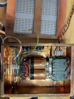
Trafo and first C box got some golden lining for some RFI protection. Lots of things in the air nowadays in modern homes for windings and rails to pickup. Maybe it can also give some fire protection to an eventual spark. Rails got bleeders. The transformer was placed on to-220 plastic washers under and above the metal. With the lid on I can no longer hear the transformer even with ear just next to it. Fixed with m3 bolts and locknuts.

Final voltage test before rigging. Lid made from some donor perf metal sheet.
Interconnects quick made with Vandamme shielded twisted pair digilog install cables. Shield and black soldered together on RCA side, shield unterminated in the box, red carries signal. Works like a charm.
Enjoying it while posting 🙂
Trafo and first C box got some golden lining for some RFI protection. Lots of things in the air nowadays in modern homes for windings and rails to pickup. Maybe it can also give some fire protection to an eventual spark. Rails got bleeders. The transformer was placed on to-220 plastic washers under and above the metal. With the lid on I can no longer hear the transformer even with ear just next to it. Fixed with m3 bolts and locknuts.
Final voltage test before rigging. Lid made from some donor perf metal sheet.
Interconnects quick made with Vandamme shielded twisted pair digilog install cables. Shield and black soldered together on RCA side, shield unterminated in the box, red carries signal. Works like a charm.
Enjoying it while posting 🙂
Attachments

If between pin 2 and pin 1 XLR out you have as much signal voltage as between center pin and barrel of RCA in and same between XLR out pin 3 and pin 1 then you got gain 1.So if I get you right, the balanced signal out between 2 and 3 shall be double that of the generators input to SE for unity gain SE to bal. The Sonifex is opamp based with reference to PE so that makes me pretty sure that since I measured between 1 (gnd) and 2 (hot) it gave me the same result. Did I get you right?
I read this article before measuring but I am still a bit confused
https://lab2104.tu-plovdiv.bg/index.php/2019/02/28/voltage-measurement-of-balanced-outputs/
Optimal would be to solder up a 10k:10k transformer but it seems abit above and beyond
Did some config changes today. Firstly I added a little opamp stereo buffer who I tapped in on the LF out on respective channel. My tqwt 15 inch spkrs has a stiff bass down to just under 40 where they fall steep. So I took the tapped extra LF channels and feed a couple of subs. They are plugged in a way so they are strong in the 20-40 region. Then I took their local xover down to lowest, which I suspect are in those regions (have only listened, not measured yet). So basically I get a 2x3 system with this. And it pumps bass very well indeed, almost got a bit scared at first. I thought maybe they should interfere alot in the base xover (which isnt really a xover) but by listening it doesnt seem like it. Gonna do some REW on it later.
I also have suspected now and then that the NE5532 opamps have had some tiny and very high fq oscillation. Not bad, they dont get warm or so, but I have heared something towards distorsion now an then, so I swapped them all to LM4562. The initial feeling was that it got leaner, not that full but also alot more control and detail. Upping the volume a tad and I had the fullness and detail in one package, so they are keepers.
The regs are doing a fantastic job!
With the LM4562s in I still wanted to check for oscillations so I pulled out a big scope. Here is the output from one of the channels. No signal in, just being on. I am not sure but I dont think it is oscillations? More like noice from rails?
It makes kind of strange square waves at higher frequencies, like sloaping squares. This is 20kHz.

At LF it make a square wave with a small rounded overshoot, looks ok to me. Would you say there is a problem?
It makes kind of strange square waves at higher frequencies, like sloaping squares. This is 20kHz.
At LF it make a square wave with a small rounded overshoot, looks ok to me. Would you say there is a problem?
Last edited:
On the rails I just cant find anything but a sub millivolt wiggle. It does not look much worse than ch B that isnt connected. Mayby it is just the RC links in the xover that makes the square waves look like that?
Edit. That makes sense to me. The squares goes rounder closer to the xover point. Thats because it starts washing it away?
Edit. That makes sense to me. The squares goes rounder closer to the xover point. Thats because it starts washing it away?
Last edited:
That's not oscillation. Oscillation is periodic. Sine like or even saw-tooth like sometimes. Generally crooked in shape but a steady repeat. The scope locks on it.
You can also spot high frequency oscillation riding on lower frequency test tones when making them fuzzy or by showing fuzzy bursts at certain places on them.
Probably some kind of noise in the measurement loop. High because you hunt at 5ns. Probe with a short ground coil. If power line ripple related it would be 100Hz.
That sloping top square shape indicates one pole high pass filtering.
Thanks. I used small ground clips. It was the strange square made by the filters together with that the opamps gets warm, around 40-43 degrees C that made me go hunt. Both has its explanations now. With a +/-15 v supply they dissipate some 300 mW so nothing strange. And the dist I suspected was probably Billie Eilish own mix, some weird sounds on those mixes. I’ll lid it up and enjoy some deep sea base. Have a nice weekend!
Last edited:
I'm setting up a test / shootout setup for some TDA1541A boards/ They use -5V 0 +5V and for -15V the pcb creator swapped polarity on the PCB so diy folks could just use a +15V supply and connect it in reverse polarity.
If I use a BiB 1.1 positive reg board for this will it be ok?
If I use a BiB 1.1 positive reg board for this will it be ok?
A positive BiB regulation section behaves no different than say an LM317 connections-wise. As a whole section it is ground independent (floating). Due to having its own bridge diodes and transformer secondary. Like a channel output of a bench power supply. Not a part of a single bridge symmetric with a ground return to a secondary's midpoint. If that swapped polarity PCB comes with no special caution for a specific grounding reference it should also work with a BiB. You could use proper mA rating fuses in-line with that PCB's power inputs during first tests. Just in case.
Working, reacts properly, but needs adjustment…
R101 14R (190mA) Load about 40mA/channel
(2) red led, 6K8, 5K pot, no zener, would like 30VDC output, can't get lower than 32.9.
Q106/206 are quite hot, is there any way to move some heat to Q101/201? Change green string? (yes, heatsink needs to be bigger...)
Any ideas would be welcome. Thanks!


R101 14R (190mA) Load about 40mA/channel
(2) red led, 6K8, 5K pot, no zener, would like 30VDC output, can't get lower than 32.9.
Q106/206 are quite hot, is there any way to move some heat to Q101/201? Change green string? (yes, heatsink needs to be bigger...)
Any ideas would be welcome. Thanks!
Last edited:
Hi, nice up to now. How much voltage drop across the 6K8? With that info we can determine the bias current in the Vref to alter that resistor and lower the output voltage adj roof.
About heat, too small sinks obviously, but you can up the value of R101 or short one green Led. What is the voltage drop across the 14R R101?
About heat, too small sinks obviously, but you can up the value of R101 or short one green Led. What is the voltage drop across the 14R R101?
Hello! Morning here, thank you for the response,
R101 (14R) Vdrop 2.75v
R103 (6K8) Vdrop 28v
R203 (6K8) Vdrop 23.7v
Downstream is discrete I/V for DAC, should C102 and or C104 be film or larger electrolytic? Both now are 10uF electrolytic for testing.
Short one green LED? Or leave it? I'm not exactly sure what it's doing ... changing the reference voltage in the series CCS...?
Hi,
R101 drop says 196mA
R103 drop says 4.117mA
R203 drop says 3.48mA
R101 you can change to 18R-20R for about 150mA CCS and save on heat (still enough overhead for a 40mA load).
You won't need to short an LED in that way. Shorting an LED cuts one VF from the (VFtotal-VGS)/R101=ICCS equation.
R103,203 you can change to 4K7 to can better utilize the trimmer since you surely got strong enough JFETs in the Vrefs.
Leave the 10uF output electrolytics in place. They are a good middle ground.
- Home
- Amplifiers
- Power Supplies
- SSLV1.1 builds & fairy tales