Make different sound, great sound . Thank you again.
We crossposted. Nice picture. What diodes are those?
We crossposted. Nice picture. What diodes are those?
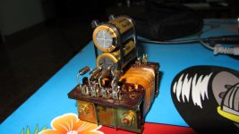
They are mRU3A . I used it for PSU 71A tube filament too.
Attachments
Sorry for late reply .
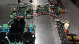
I replaced Salas BiB for CLCLC-LT1804 regular, which power supply for WaveIO Card , more detail, I like high and mid range . It is really improved .
Now, I used Salas BiB for Buffalo IIISE and Ian Clock Kit . TPA Placid HD for WaveIO Card .
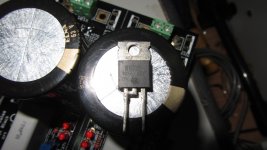
I am soldering +- board . I have two type diode , The B10100 -Schottky and HFA08TB60 -Ultrafast Soft Recovery , What type diode is best for I/V TPA Legato power supply ? .
I replaced Salas BiB for CLCLC-LT1804 regular, which power supply for WaveIO Card , more detail, I like high and mid range . It is really improved .
Now, I used Salas BiB for Buffalo IIISE and Ian Clock Kit . TPA Placid HD for WaveIO Card .
I am soldering +- board . I have two type diode , The B10100 -Schottky and HFA08TB60 -Ultrafast Soft Recovery , What type diode is best for I/V TPA Legato power supply ? .
Attachments
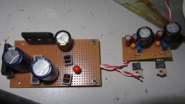

I just finished soldering +- boards with IRF kits. I set +-14.75 VDC (315mA CCS, load 190mA) . The negative board is ok, the voltage DC down to 14.72 VDC after 30 minutes, but the positive board is backwards, the voltage DC increase to 14.85 VDC after 30 minutes and I think it will continue to increase.
Last edited:
Hi Salas,
I can't explain what I see... .
.
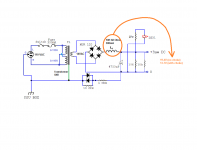
May be you can clarify for me...(still testing my Raw PSU for BHL MC).
The target: I need to have a little less than 20v out from my Raw PSU.
Please see my drowning.
So, I placed Hammond choke (10H 300mA 68Ohm) for test (take it from friend of mine) and my V-out dropped to 13.7v from 19.4v. By calculation I should loosea bit, but not about 5-6 v.
So, connected my two secondaries in series (14V and 9V) in order to get 23v out from transformer. After rectification (23*1.4-1.4) I got about 32v (my AC is quite healthy -> 121-122v). Then I placed choke and got about 20v.
It is what I need, but can't explain it. Does choke resistance increasing during operation with current? What do I miss here?
Thank you.
P.S. No noise from MC with choke in Raw PSU. Very quite....!!!!
I can't explain what I see...
. May be you can clarify for me...(still testing my Raw PSU for BHL MC).
The target: I need to have a little less than 20v out from my Raw PSU.
Please see my drowning.
So, I placed Hammond choke (10H 300mA 68Ohm) for test (take it from friend of mine) and my V-out dropped to 13.7v from 19.4v. By calculation I should loosea bit, but not about 5-6 v.
So, connected my two secondaries in series (14V and 9V) in order to get 23v out from transformer. After rectification (23*1.4-1.4) I got about 32v (my AC is quite healthy -> 121-122v). Then I placed choke and got about 20v.
It is what I need, but can't explain it. Does choke resistance increasing during operation with current? What do I miss here?
Thank you.
P.S. No noise from MC with choke in Raw PSU. Very quite....!!!!
Attachments
Last edited:
The 4700uF capacitor before choke input (C-L). I think the Voltage DC will be increase .
Like this?
Typically, to kill high ripple people use LC filters.
CL is Chebyshev pass or high cut filters.
Attachments
Last edited:
I just finished soldering +- boards with IRF kits. I set +-14.75 VDC (315mA CCS, load 190mA) . The negative board is ok, the voltage DC down to 14.72 VDC after 30 minutes, but the positive board is backwards, the voltage DC increase to 14.85 VDC after 30 minutes and I think it will continue to increase.
Set for when hot. Change one LED for a common silicon diode if still sliding on the positive. Depends on thermals in some builds and on transistor samples. Also on trimmer and resistor ppm.
Choke input is more ineficient than CLC.
I'll try it tomorrow.
So, should I not see such big V drop with CLC?
- Home
- Amplifiers
- Power Supplies
- SSLV1.1 builds & fairy tales