@Djim : the #14 post looks interesting, my main thought is what that might mean in terms of characteristics, what will it influence ?
It takes away a minimum of volume in the system wich is appealing, also I inclined to think that it may also act as a form of diffuser, reducing unwanted resonances.
On the other hand I'm curious as to the effects on cone balance when you "use them in anger" as I believe it is called, meaning when you push the system to it's limits, will the semi-enclosed volume act with grater force then the open slanted side leading into the horn ?
In either case, very interesting, even if only having (probably) a minute positive contribution, if any, it's a rather simple thing to try if one where to build new ones.
Thanks !
I myself skipped the car audio era of my time, I was to busy trying to figure out how to get the attention of the ladies, which might have been a catch 22 now that i think about it 🙂
I was however frequently involved in designing several of my friends systems, eehhh... so that they could *facepalm* get the above mentioned attention... darn... (currently looking like the guy in post #12)
Last edited:
ok... now this cone correction looks interesting , found a post about it earlier.
It seems Mr Danley had a cut-through section on his TH118 .. but has since taken it off the site .. DAMN!! .. would have been interesting to learn a bit more about this.
If anyone has any information please feel free to message me.
Not sure whether to continue the builds (finally started cutting today) or wait and find out more about cone correction
Hi Anders,
My examples for the cone volume correction in my earlier post were just a quick brainwave and I have not worked them out yet. Was more meant to create awarenesses to the cone volume.
As you mentioned in an earlier post, your Tham is a little more difficult to simulate with HornResp. Although I agree that HornResp has limited horn parameters you still can get a relative accurate picture if you model it with the correct volumes at S2 and S4 as result of the cone volume (2) and the volume taken by the driver (S4). The importance in modelling is not to get very accurate areas at just the locations of S1, S2 S3, S4 and S5 but instead, you better strive to more or less accurate volumes per section. If you do so, it will end in a more accurate internal volume of the system.
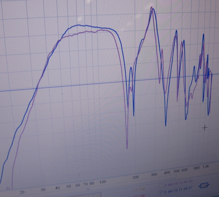
For instance the Tham's internal dimensions are 51,4 x 64,4 x 46,4 cm which ends in a system volume of about 154 Litre. With that in mind, and the volume taken by the driver at S4, I made a new model that is very close to its measurement:

The roll-off at the low end is not correct as result of the changing stiffness of the internal volume as frequency goes down. This will result in a better response compared to its measurement but can simulated by increasing the Le value by factor two for instance. It should be noted that changing the Le value can only be used to analyse the result for the roll-off.
My examples for the cone volume correction in my earlier post were just a quick brainwave and I have not worked them out yet. Was more meant to create awarenesses to the cone volume.
As you mentioned in an earlier post, your Tham is a little more difficult to simulate with HornResp. Although I agree that HornResp has limited horn parameters you still can get a relative accurate picture if you model it with the correct volumes at S2 and S4 as result of the cone volume (2) and the volume taken by the driver (S4). The importance in modelling is not to get very accurate areas at just the locations of S1, S2 S3, S4 and S5 but instead, you better strive to more or less accurate volumes per section. If you do so, it will end in a more accurate internal volume of the system.
For instance the Tham's internal dimensions are 51,4 x 64,4 x 46,4 cm which ends in a system volume of about 154 Litre. With that in mind, and the volume taken by the driver at S4, I made a new model that is very close to its measurement:
The roll-off at the low end is not correct as result of the changing stiffness of the internal volume as frequency goes down. This will result in a better response compared to its measurement but can simulated by increasing the Le value by factor two for instance. It should be noted that changing the Le value can only be used to analyse the result for the roll-off.
Last edited:
Measurement from Anders Martinsson 🙂. Purple line is based on the 'old' design as used in the sim of above.
JohnnyPyro, have you built the test boxes yet? I too have 8 15PZB40's looking for new bass cabs and have been wondering what they sound like in these designs. They sim real nice in the THAM15 and Xoc1's TH-18.
It seems Mr Danley had a cut-through section on his TH118 .. but has since taken it off the site .. DAMN!! .. would have been interesting to learn a bit more about this.
Is this what you are looking for?
TH 115
Cheers
William Cowan
William,
Is the TH-118 any different internally than the TH-115 ?
Art
William,
Is the TH-118 any different internally than the TH-115 ?
Art
G'day Art
I've read that they are the same. I could imagine the driver mounting panel is quite different though.
Cheers
William Cowan
Dennis,They are a different length, that can be seen in the impedance curves.
The TH-115 spec sheet has an impedance curve, but don't see one on the TH-118 spec sheet, do you have one you could post?
Art
Alas, I didn't think to save it, and Danley has since changed his site.
IIRC, the minima was at 28hz.
IIRC, the minima was at 28hz.
IIRC, Tom Danley told me the TH-118 was basically identical inside to the TH-115, though the impedance minima for the TH-115 is listed at 78 Hz, and 67 for the TH-118 😉.Alas, I didn't think to save it, and Danley has since changed his site.
IIRC, the minima was at 28hz.
Art
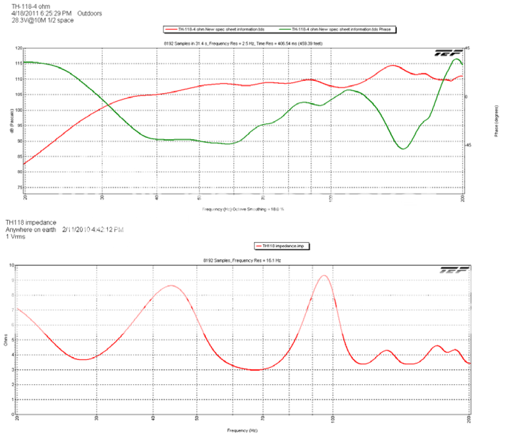
" though the impedance minima for the TH-115 is listed at 78 Hz, and 67 for the TH-118 ."
I was referring to the 1/4W impedance minima, which looks close to 28hz in the graph on post #33 (thanks to NEO Dan for the graph!).
On the older TH-115 sheet that I have, this minima is at about 36hz, hence the conclusion they are not the same length.
I was referring to the 1/4W impedance minima, which looks close to 28hz in the graph on post #33 (thanks to NEO Dan for the graph!).
On the older TH-115 sheet that I have, this minima is at about 36hz, hence the conclusion they are not the same length.
Last edited:
On the older TH-115 sheet that I have, this minima is at about 36hz, hence the conclusion they are not the same length.

th118 has a constriction in the path at the last bend.
Why?
What does that achieve?
Is it modeled in a sim?
Why?
What does that achieve?
Is it modeled in a sim?
From ProSoundWeb
The TH-118 kind of fell into my lap,” laughed inventor Tom Danley. “Eighteen Sound introduced a new 18-inch driver that is tremendously powerful. I looked at the computer model of the TH-115, which is, of course, well suited to a 15-inch driver.
“Remarkably, when you drop the new parameters in, the model calls for essentially the same box that we are already using for the TH-115. We prototyped one with the 18-inch driver, and the sound was simply amazing.”
Hi Andrew,th118 has a constriction in the path at the last bend.
Why? What does that achieve? Is it modeled in a sim?
It is no more than a practical solution in order to make an 18" fit. The restriction is less than 1/6th of the path (and probably follows the round curve of the driver's edge) so its influence is very minimal.
The graphs use different smoothing, which accounts for some difficulty in comparison.I guess the question still remains, why do they graph so different in impedance then?
Using Hornresp, the Keystone simulation impedance maxima for a B&C 18SW115-4 is about 3 Hz lower than for an Eminence 4015LF, less of a difference than the TH-118 /TH-115, but a difference.
For what it's worth, the simulation reflects the actual FR measurement, though I never have tested impedance.
- Status
- Not open for further replies.
- Home
- Loudspeakers
- Subwoofers
- SS15 or Tham 15?